- 43 -
Setting
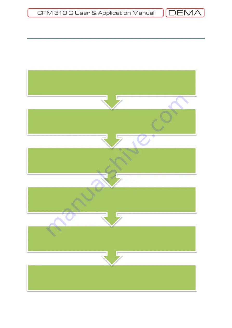
After completing the mounting and cabling phases, relay settings can be done. Follow the procedure
explained below. Each step has its own dedicated section to explain setting processes, as stated with
page numbers.
To ensure reliable operation, double check and note your settings.
↺
Settings Check and Archieving
Protection Settings, p.66
Applying the protection functions I>, I>>, I>>>, I
e
>, I
e
>>,I
e
>>>, I
2
>, I
2
>>, %(I
2
/
1
)>, I<, I
θ
>
Automatic Control Settings, p.101
Setting the parameters for cold load pickup, programmable inputs & outputs, tripping, blocking logic
selectivity, CB failure, auxiliary timer, delaying logic selectivity, auto-recloser, CB Supervision,
programmable LEDs, latching and alarm.
System Settings, p.96
Setting the parameters for time, date, network power frequency, relay description, password,
symbolization, settings group, phase rotation, backlighting, operating language, setting password
on/off and CB password On/off on the
System Settings Menu
, or loading the default settings.
Curent Transformer Settings, p.99
Setting the primary and secondary nominal currents for phases and earth, setting the earth
protection setting range on the relay menus.
Dip-switch Settings, p.47
1 A / 5 A selection for phase and earth nominal current setting, (0.02-8) I
en
or (0.1-40) I
en
selection for
determining the earth protection setting range.
Summary of Contents for CPM 310 G
Page 1: ...CPM 310 G Digital Overcurrent Protection Relay User Application Manual vEN 2016 03...
Page 2: ...2...
Page 6: ...6 ABOUT DEMA...
Page 11: ...11 INTRODUCTION...
Page 32: ...32 PACKING LABELING INFORMATION...
Page 34: ...34 OPERATING MANUAL...
Page 53: ...53 RELAY MENUS MANUAL...
Page 55: ...55 The Menu Tree...
Page 56: ...56...
Page 57: ...57...
Page 58: ...58...
Page 59: ...59...
Page 60: ...60...
Page 61: ...61...
Page 128: ...128 DIGICONNECT PC PROGRAM MANUAL...
Page 189: ...189 APPLICATION DIAGRAMS...
Page 191: ...191 Sample Power Transformer Protection Application Diagram...
Page 193: ...193 FUNDAMENTAL CABLING DIAGRAM...
Page 203: ...203 APPLICATION DIAGRAM NO 10 RS485 Cabling...
Page 204: ...204 TECHNICAL DATA...
Page 220: ...220 GLOSSARY...


