- 62 -
Reset Menu (Reset Cycle)
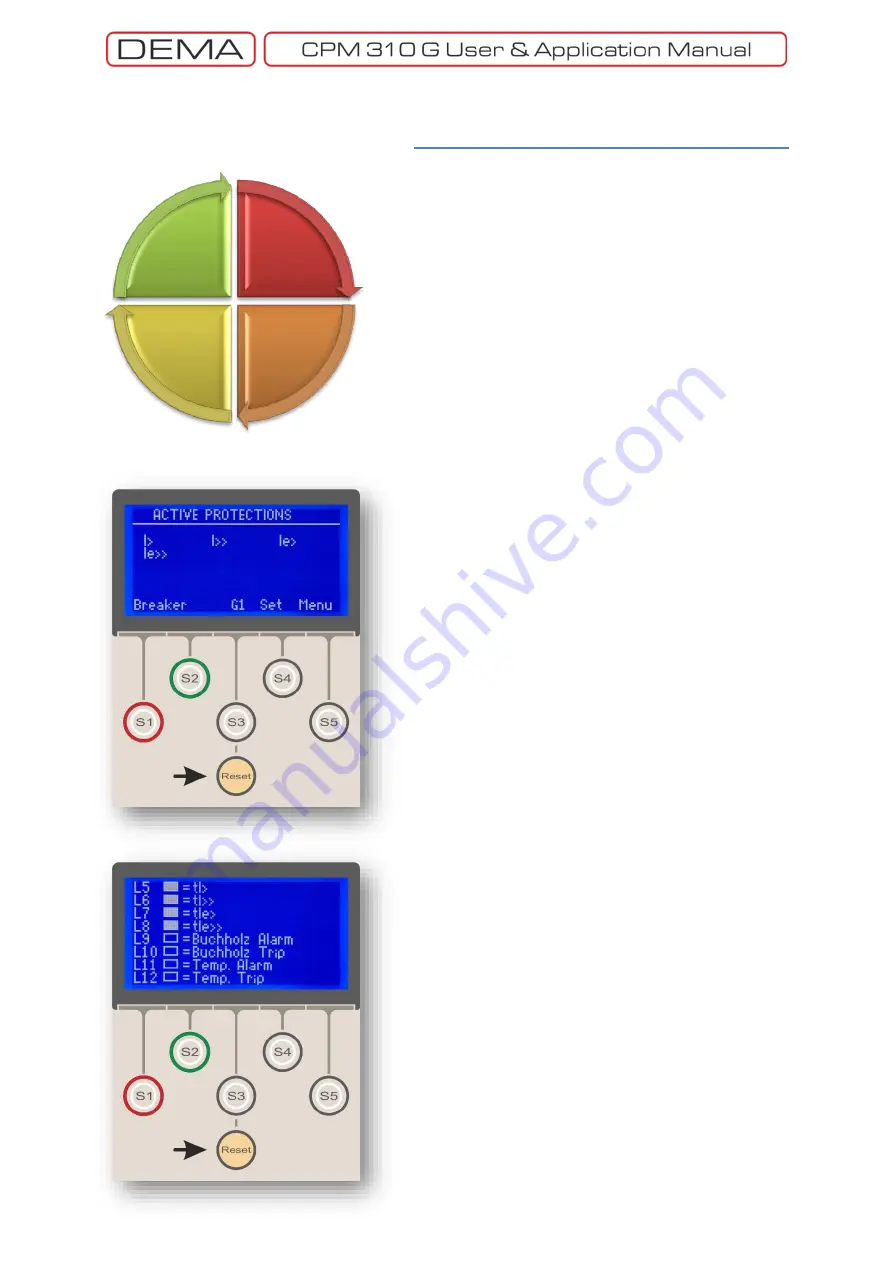
Reset Menu is reached by pressing the
Reset
button
while at any menu. The location of the
Reset
button is
pointed in the middle picture. The menu displays any
active alarms generated by active protection and
supervision functions, and lets the user read and delete
these alarms. Exploration, viewing and resetting
functions are achieved via Reset button only - the cyclic
functionality of Reset button eliminates the need of
cover removal to perform Alarm Menu tasks. The reset
button cycle is shown on the left.
The schema at the top summarizes the cycle of
functionality of the
Reset
button.
While any screen is being viewed (hereby described
as “Initial Screen”), pressing the
Reset
button once will
lead to the display of
LED Status
screen, as shown at
the bottom picture.
The sample LED status picture shows that there are 4
active programmable LEDs (L5 – L8), that tell the tI>,
tI>>, tIe> and tIe>> protection functions have
generated a trip signal. Other programmable LEDs (L9
– L12) have no activity. See the LED Status Menu
section for more information.
When the
Reset
button is pressed for the second
time, one of the following will happen:
o
If there are any alarm to be viewed, the screen will
display the
Alarms
menu (the top picture on the
following page). The picture shows a sample situation
where there are 8 alarms to be read which are
numbered as 01/08, 02/08 … 08/08 on the right side of
the screen. Each of the alarms summarizes a trip event
and its source (e.g. “tIe>> trip with 2.657 kA tripping
current”). Since there are more alarms than can be
displayed on a single page, the Alarms Menu will have
several pages, of which can be read through by
pressing the Reset button several times until the last
page is reached.
Pressing the Reset button again after the viewing all of
the alarms will lead to the screen given at the middle of
the page, displaying this massage:
Press RESET for a long time to delete all alarms.
If the reset button is pressed continuously for 2
seconds when this massage appears, all alarm records
will be deleted. If some of the alarms cannot be
deleted after this action, this will mean that some of
the alarm sources are still active.
↺
o
When the
Reset
button is pressed for the second
time and there are no alarms to be viewed, the screen
Initial
Screen
LED Menu
Alarms (if
available)
Active
Protections
Reset Button Function Cycle
Summary of Contents for CPM 310 G
Page 1: ...CPM 310 G Digital Overcurrent Protection Relay User Application Manual vEN 2016 03...
Page 2: ...2...
Page 6: ...6 ABOUT DEMA...
Page 11: ...11 INTRODUCTION...
Page 32: ...32 PACKING LABELING INFORMATION...
Page 34: ...34 OPERATING MANUAL...
Page 53: ...53 RELAY MENUS MANUAL...
Page 55: ...55 The Menu Tree...
Page 56: ...56...
Page 57: ...57...
Page 58: ...58...
Page 59: ...59...
Page 60: ...60...
Page 61: ...61...
Page 128: ...128 DIGICONNECT PC PROGRAM MANUAL...
Page 189: ...189 APPLICATION DIAGRAMS...
Page 191: ...191 Sample Power Transformer Protection Application Diagram...
Page 193: ...193 FUNDAMENTAL CABLING DIAGRAM...
Page 203: ...203 APPLICATION DIAGRAM NO 10 RS485 Cabling...
Page 204: ...204 TECHNICAL DATA...
Page 220: ...220 GLOSSARY...


