- 89 -
Positive & Negative Sequence (P/N) Current Measurements
Menu
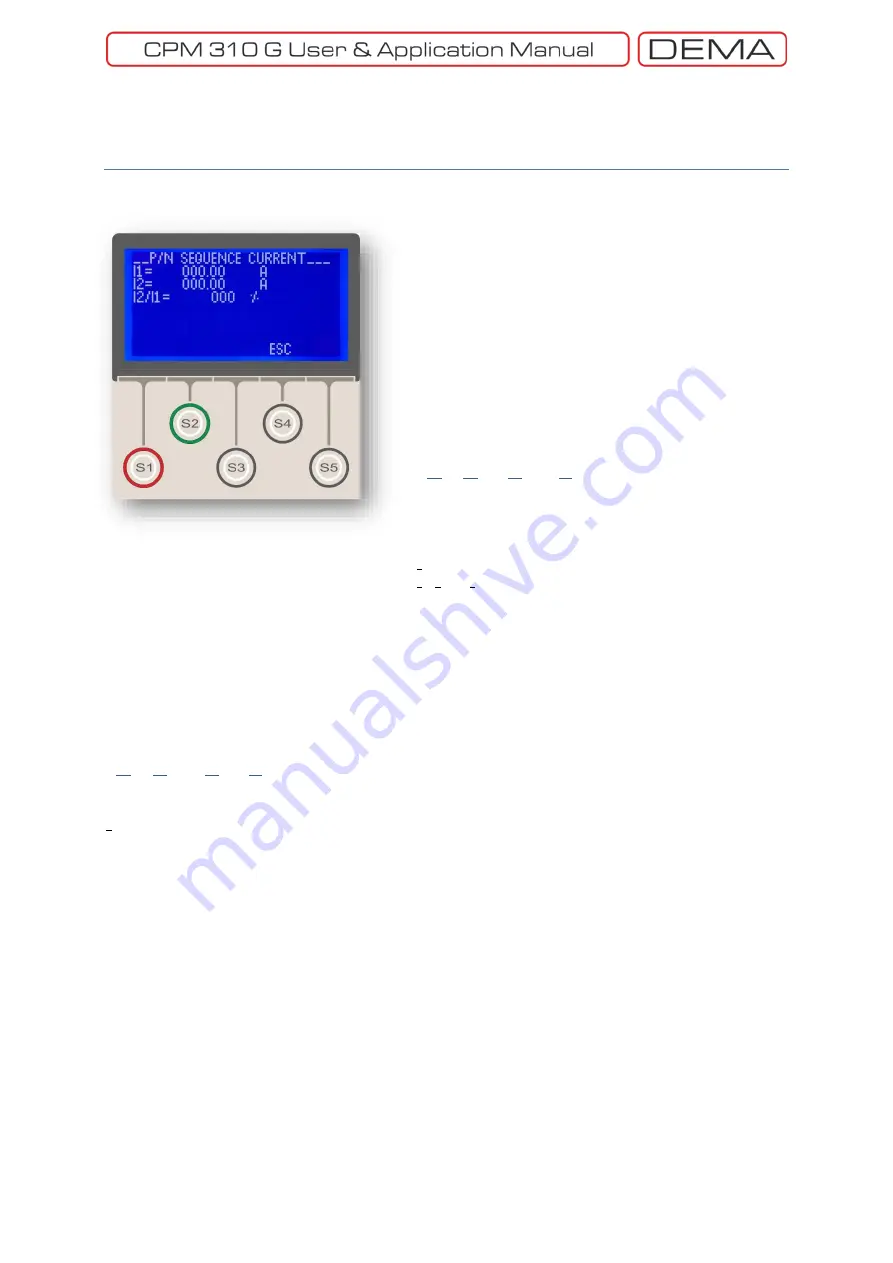
Positive and Negative Sequence Current Measurements
Menu
screen is shown on the left picture.
The menu monitors the following measurements.
I1 (Positive Sequence Measurement)
Positive sequence component of the phase current
values is formulated as follows.
𝑰
𝒓
(𝒕) = 𝑰
𝒑
× 𝐬𝐢𝐧[𝝎𝒕 − 𝝓]
[1]
𝑰
𝒔
(𝒕) = 𝑰
𝒑
× 𝐬𝐢𝐧[𝝎𝒕 − (𝝓 + 𝟏𝟐𝟎°)]
[2]
𝑰
𝒕
(𝒕) = 𝑰
𝒑
× 𝐬𝐢𝐧[𝝎𝒕 − (𝝓 + 𝟐𝟒𝟎°)]
[3]
𝟑𝑰
𝟏
= 𝑰
𝒓
+ 𝒂𝑰
𝒔
+ 𝒂
𝟐
𝑰
𝒕
[4]
Where,
I
r,s,t
(t)
the momentary values of phases’ current,
I
p
current peak value,
I
1
positive sequence current vector,
I
r
, I
s
ve I
t
phase current vectors,
a
an operator that rotates a vector by 120°,
a
2
an operator that rotates a vector by 240°.
I
1
gets the same value with the phases when the phase current values get the same value; while
having the average value of the phases’ when load imbalance takes place.
I2 (Negative Sequence Measurement)
Negative sequence component of the phase current values is formulated as follows.
𝟑𝑰
𝟐
= 𝑰
𝒓
+ 𝒂
𝟐
𝑰
𝒔
+ 𝒂𝑰
𝒕
[5]
Where,
I
2
: represents the negative sequence current vector.
I
2
gets zero value when the phase current values the same value; while having values greater than 0
when load imbalance takes place.
I2/I1 (Negative Sequence / Positive Sequence)
I
2
/ I
1
(Negative Sequence / Positive Sequence) value is monitored on this row. The momentary value
is displayed in percentages. □
Main Screen » Menu »
Measurements » P/N Sequence
Current
Summary of Contents for CPM 310 G
Page 1: ...CPM 310 G Digital Overcurrent Protection Relay User Application Manual vEN 2016 03...
Page 2: ...2...
Page 6: ...6 ABOUT DEMA...
Page 11: ...11 INTRODUCTION...
Page 32: ...32 PACKING LABELING INFORMATION...
Page 34: ...34 OPERATING MANUAL...
Page 53: ...53 RELAY MENUS MANUAL...
Page 55: ...55 The Menu Tree...
Page 56: ...56...
Page 57: ...57...
Page 58: ...58...
Page 59: ...59...
Page 60: ...60...
Page 61: ...61...
Page 128: ...128 DIGICONNECT PC PROGRAM MANUAL...
Page 189: ...189 APPLICATION DIAGRAMS...
Page 191: ...191 Sample Power Transformer Protection Application Diagram...
Page 193: ...193 FUNDAMENTAL CABLING DIAGRAM...
Page 203: ...203 APPLICATION DIAGRAM NO 10 RS485 Cabling...
Page 204: ...204 TECHNICAL DATA...
Page 220: ...220 GLOSSARY...


