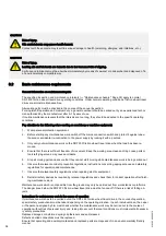
Switch off the electric power supply before starting work. The mains connection or isolating switch must be pro‐
tected against unauthorised or accidental restoration of the power supply by means of a padlock.
Mechanical safety
All bolted connections must be correctly tightened.
Self-locking nuts must not be replaced by other types of nut. Self-locking nuts must be replaced when they have
been tightened and untightened five times. The clamping torque of a self-locking nut must not be lower than the
loosening torque specified by EN ISO 2320.
A sufficiently secure connection can only be guaranteed by tightening to the specified tightening torque.
Bolted connections must not be lubricated as otherwise the specified tightening torque values will be too high.
Check to ensure that pin connections are correctly fitted.
All assembly work must be completed in accordance with the assembly instructions. Operation with defective or
damaged DRF 200 friction wheel travel drives results in a high risk of accidents with personal injuries and dam‐
age to the installation and is, therefore, strictly prohibited.
Any change or modification which prejudices safety must be reported to the nearest person responsible immedi‐
ately. Repairs may only be carried out by experienced technicians.
Ensure that all attachment points are freely accessible for inspections and servicing or that free access can be
provided.
Protective earth conductor
The protective earth conductor in insulated leads and cables must be coloured green and yellow along its entire
length.
The protective earth conductor must not be connected to mounting bolts or screws.
Protective earth connections must be protected against accidental loosening (e.g. by using serrated lock washers
to DIN 6798). It must be possible to disconnect each individual connection.
Protective earth conductors must not carry any current in normal operation.
The same number of protective earth connection points must be provided as electric power infeed and outfeed
points.
Continuity of the PE conductor connection must be checked.
Mains connection switch
A mains connection switch must always be provided for the mains power supply line to the installation. The mains
connection switch must be arranged to disconnect all poles of your hoist unit from the mains supply.
Ensure that the mains connection switch is installed in an easily accessible position in the vicinity of your hoist
unit and that it is clearly marked.
Isolating switch
If two or more lifting appliances are fed from a common supply line, each one should be provided with an isolating
switch. This makes it possible to carry out maintenance work on individual units, without affecting operation of the
rest of the system.
Power supply line
The power supply line/cable to be used depends on the motor size, see the "Key motor data" section.
5.3
Tightening torques
Tightening torques
[Nm]
Gearbox housing
15
ZBF 63/71 motor/gearbox
15
ZBF 80 motor/gearbox
80
Hub/output shaft
45
Friction wheel/hub
70
Suspension/gearbox housing
70
Suspension fork/suspension
270
Tab. 16
CAUTION
Loose connections
Loose connections are a danger to life and limb and a risk of damage to the machine.
Metal nuts featuring a locking element (self-locking nuts) must not be replaced by normal nuts.
24
214
39
5 44/120
914
Summary of Contents for DRF 200
Page 51: ...214 395 44 120914 51...


