/Kits/1296-144CK.doc
3
8/15/2011
Assembly Tips
It is recommended to read the entire document before you begin to assemble the kit, but
the following few paragraphs is a compilation of assembly techniques used and required to
assemble this kit. These various assemble techniques will be used for more than one component
and may determine the outcome of this kit. Review the examples shown and become familiar with
the components described in the text.
Soldering surface mounted active components
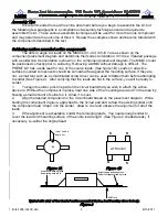
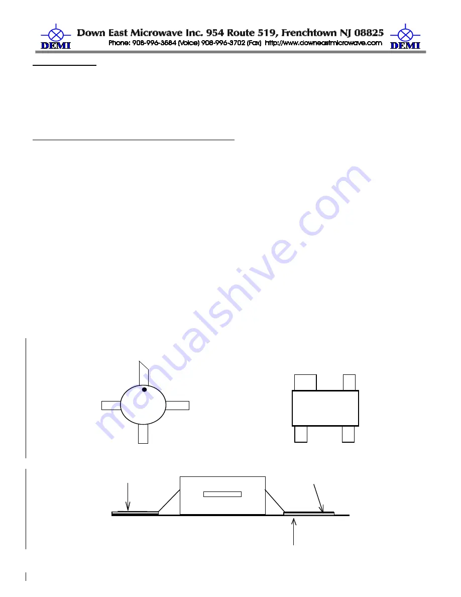
The dots or angle cut leads on the MMICs IC1-IC3, IC5-IC7 are as shown on the
component placement diagram and determine their correct orientation. IC10 is a 3 leaded package
with a solder tab. Its orientation is shown on the component placement diagram. The MMIC’s must
be positioned correctly prior to soldering. Removing a MMIC without damage is difficult. The
PHEMT Q3 has a wide lead for one of the source leads. (See figure 1B) Leads on all active
surface mounted components should be somewhat flat against the mounting surface, if they are
not, a small tool such as a small bladed screw driver can be used to flatten them before attempting
to solder (See Figure 2). After verifying that the leads are flat to the surface, you will be ready to
solder.
1.
To begin to solder, pick one pad on the circuit board that you wish to attach the active
device to. Without the component in place, heat one side of the mounting area and Tin the area by
flowing a small amount of solder on it. Allow it to cool.
2.
Align the desired component on the circuit board based on the placement diagram. While
holding the component in place, apply heat to the tinned pad and re-flow the existing solder until
the component lead “drops” into the solder. Allow to cool and observe the alignment of all of the
leads.
3.
If the alignment is acceptable, solder the remaining leads. You need enough solder to
cover the lead and mounting surface of the entire lead length. (See Figure 2 shaded areas) If
necessary, re-solder the original lead.
03
Input Lead is
angle cut
S
D
G
S
ATF34143
Figure 1A
Figure 1B
PCB Trace
Leads flat to trace, 4 places
Some spring back is OK
Solder shown in shaded areas
Solder full length of lead, 4 places
Typical side view of four leaded surface mounted device, lead bending close to body.
Figure 2
Summary of Contents for 1296-144 CK
Page 16: ......


