36
?5:6
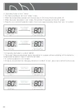
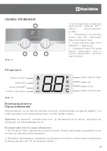
On installation, your installer will have filled the boiler and system to its effective working pressure
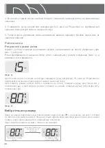
(between 1 and 2 bars) The boiler’s pressure should be regularly checked on the LCD by pressing the
‘eco/comfort –reset’ button for two seconds to ensure that this pressure is maintained between 1 and
2 bars. It is possible to return the main menu by pressing the ‘eco/comfort –reset’ button for once. If
there is a significant loss in pressure, the boiler will lock out
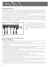
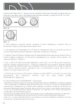
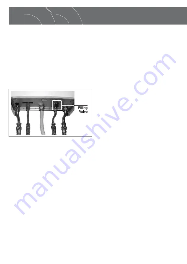
The system may be re-charged by opening the filling valve at the bottom of the boiler (Figure8) to
charge the system back up to 1.5 bars as indicated on LCD. DON’T OVERCHARGE THE BOILER
PRESSURE BEYOND 2,5 BARS AS BOILER WILL NOT OPERATE. DON’T CLOSE ANY OF THE
FOUR VALVES DIRECTLY CONNECTING TO THE BOILER. If the boiler frequently loses pressure
then your installer should be consulted.
To fill the boiler, turn the filling valve to
anti-clockwise till the desired pressure value has
been reached (between 1 and 2 bars). Don’t
forget to close filling valve by turning the valve
clockwise. Otherwise, the pressure continuously
increases
Information for Installation
5
Ř$GRQLV%ERLOHUPXVWEHLQVWDOOHGLQDURRPZKLFKKDVSXUSRVHPDGHYHQWLODWLRQIRUFRPEXVWLRQ
air. The boiler must not be sited in a room containing a bath or shower.
Ř7KHERLOHULVQRWVXLWDEOHIRUH[WHUQDOLQVWDOODWLRQXQOHVVSURWHFWHGE\DSXUSRVHPDGHEXLOGLQJVXFK
as a boiler house.
Ř)RUPDLQWHQDQFHSXUSRVHVWKHERLOHUPXVWEHLQVWDOOHGZLWKDPLQLPXPFOHDUDQFHRIPPDERYH
300mm below, 600mm to the front and 50mm to each side of the boiler case.
Ř7KHERLOHUPXVWEHVLWHGDWOHDVWPDZD\IURPƃDPPDEOHPDWHULDOVDQGKHDWVHQVLWLYHZDOOVPXVW
be protected by appropriate insulation.
Ř7KHERLOHUPXVWRQO\EHPRXQWHGRQDZDOOWKDWLVFDSDEOHRIVXSSRUWLQJWKHERLOHUőVZHLJKW
Ř7RDYRLGH[FHVVLYHFRQGHQVDWLRQRFFXUULQJZLWKLQWKHERLOHUƃXHWKHERLOHUVKRXOGZKHUHYHUSRVVL
-
ble, be sited to ensure the shortest possible flue run is utilized.
Ř)RUFRPSDUWPHQWLQVWDOODWLRQWKHUHTXLUHPHQWVEHORZPXVWEHPHWLQSDUWLFXODU
Ř
The compartment must be of sufficient size to permit access for inspection and servicing or the
removal of the boiler and any ancillary equipment.
Ř
Any space used for airing clothes or storage must be separated from the appliance by a
non-combustible partition. Where the partition is formed from perforated material, then the major
dimension of the apertures shall not exceed 13 mm.
Ř
Where the boiler’s flue pipe passes through the airing space, it must be protected by a
non-combustible sleeve or fire stop having a minimum clearance of 25 mm between the flue pipe and
(Figure 8)
Summary of Contents for Adonis B24
Page 1: ...Adonis B24 Instruction for Use Duvar Tipi Kombi Wall Hung Combination Boiler 0020146277_01...
Page 2: ......
Page 3: ...Adonis B 24 Duvar Tipi Kombi TR...
Page 22: ...Adonis B 24 Wall Hung Combination Boiler EN...
Page 41: ...Adonis B 24 UA...
Page 58: ...58 1 9S 6 1 9 0 1 19 33...
Page 59: ...59 E8 U Q F...
Page 60: ...Adonis B 24 6 f RU...
Page 78: ...Q 0 0 Q 0 0 0 Q 7 0 4 6 Q 4 O 6 0 78 Q Q R 0 Q...
Page 79: ......

