Installation 5
0020219190_00 Installation and maintenance instructions
17
The flue gas connection is implemented via a branch con-
nection on the single or header line in natural draught opera-
tion. The diameter of the line is to be determined depending
on the total output of the connected units.
For each additional 90° elbow (or two 45° elbows) that is
required, the length
(L1+L2)
must be reduced by 2 m (for
80/80 mm diameter).
Length of the air/flue gas installation, dia. 80/80 mm
(
→
Page 36)
5.7
Electrical installation
In Turkey, the electrical installation must only be carried out
by authorised and qualified electricians.
Danger!
Risk of death from electric shock!
The mains connection terminals L and N re-
main live even if the product is switched off.
▶
Switch off the power supply.
▶
Secure the power supply against being
switched on again.
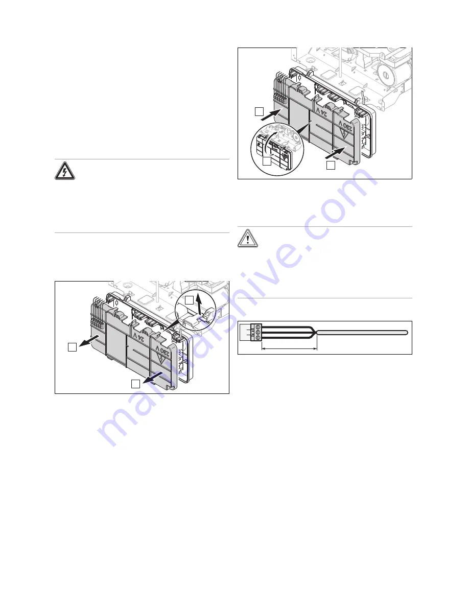
5.7.1 Opening/closing the electronics box
5.7.1.1 Opening the electronics box
1.
Remove the front casing. (
→
Page 10)
4x
A
B
B
2.
Open the electronics box as shown in the illustration.
5.7.1.2 Closing the electronics box
A
A
B
1.
Close the electronics box as shown in the illustration.
2.
Install the front casing. (
→
Page 11)
5.7.2 Carrying out the wiring
Caution.
Risk of material damage caused by incor-
rect installation.
Mains voltage at the incorrect plug terminals
on the product may destroy the electronics.
▶
Only connect the mains connection line to
the terminals marked for the purpose.
1.
Shorten the supply lines to the appropriate length.
30 mm max.
2.
Ensure that the outer sheathing on the flexible lines is
correctly stripped in order to prevent short circuits if a
strand becomes loose.
–
Stripping:
≤
30 mm
3.
Ensure inner conductor insulation is not damaged when
stripping the outer sheathing.
4.
Only strip inner conductors just enough to establish
stable connections.
5.
To avoid short circuits resulting from loose individual
wires, fit conductor end sleeves on the stripped ends of
the conductors.
6.
Screw the respective plug to the supply line.
7.
Check whether all conductors are sitting mechanically
securely in the terminals of the plug.
8.
Plug the plug into the associated PCB slot.
9.
Secure the cables in the electronics box using the strain
reliefs.


