3. Maintenance and troubleshooting
MERMAID E1100-I
STD00
Page 22 of 54
Service instructions
Dismantling of Crank Mechanism
Step A)
Drain oil, and then remove:
- pump shaft key
- rear cover
- connecting rod cap
- side covers, using M6x 50 screws, inserting them in the apposite holes as shown in fig. 2
Step B)
Push Piston Guides & Connecting rods forward, in order to extraction the pump shaft lateral .
2 marks are visible on the crankshaft, as shown in fig. 3; they must be turned towards the
operator in order to facilitate extraction. Before extract Piston Guide, remove ceramic piston
and wiper 1
st
.
Crank Mechanism Assembly
Step A)
Thoroughly fit the piston guide seals into their seat on the crankcase as shown in ( fig. 5/a )
Step B)
Introduce the pre-assembled piston guide / connecting rod units into their seat; to facilitate
tightening of the connecting rod cap, we advise to position the connecting rod so you can
easily read the number. To easily introduce the crankshaft, without the key, fully push the
piston guide / connecting rod unit.
Step C)
Before reassembly of the side covers, check the seal lips for wear. If replacement is
necessary, position the new ring as shown in fig. 5. Make sure the shim rings have been
inserted, before assembling the cover (sight glass side).
Summary of Contents for MERMAID E1100-I
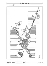
Page 38: ...4 Spare parts list MERMAID E1100 I STD00 Page 37 of 54 Pump assembly ...
Page 46: ...4 Spare parts list MERMAID E1100 I STD00 Page 45 of 54 ...
Page 47: ...4 Spare parts list MERMAID E1100 I STD00 Page 46 of 54 ...
Page 53: ...5 Wiring Diagram MERMAID E1100 I STD00 Page 52 of 54 5 Wiring Diagram ...


