BATTERY
TAP TO SWITCHED
+12V SOURCE WIRE
POWER
HUB
2
//
Power Distribution Module //
ELC.00.30000
Constant Example
SW12V POWER
TAP TO SWITCHED
+12V SOURCE WIRE
GROUND WIRE
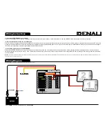
Wiring Instructions
Note: This drawing is not to scale. Components are enlarged for illustrative purposes only.
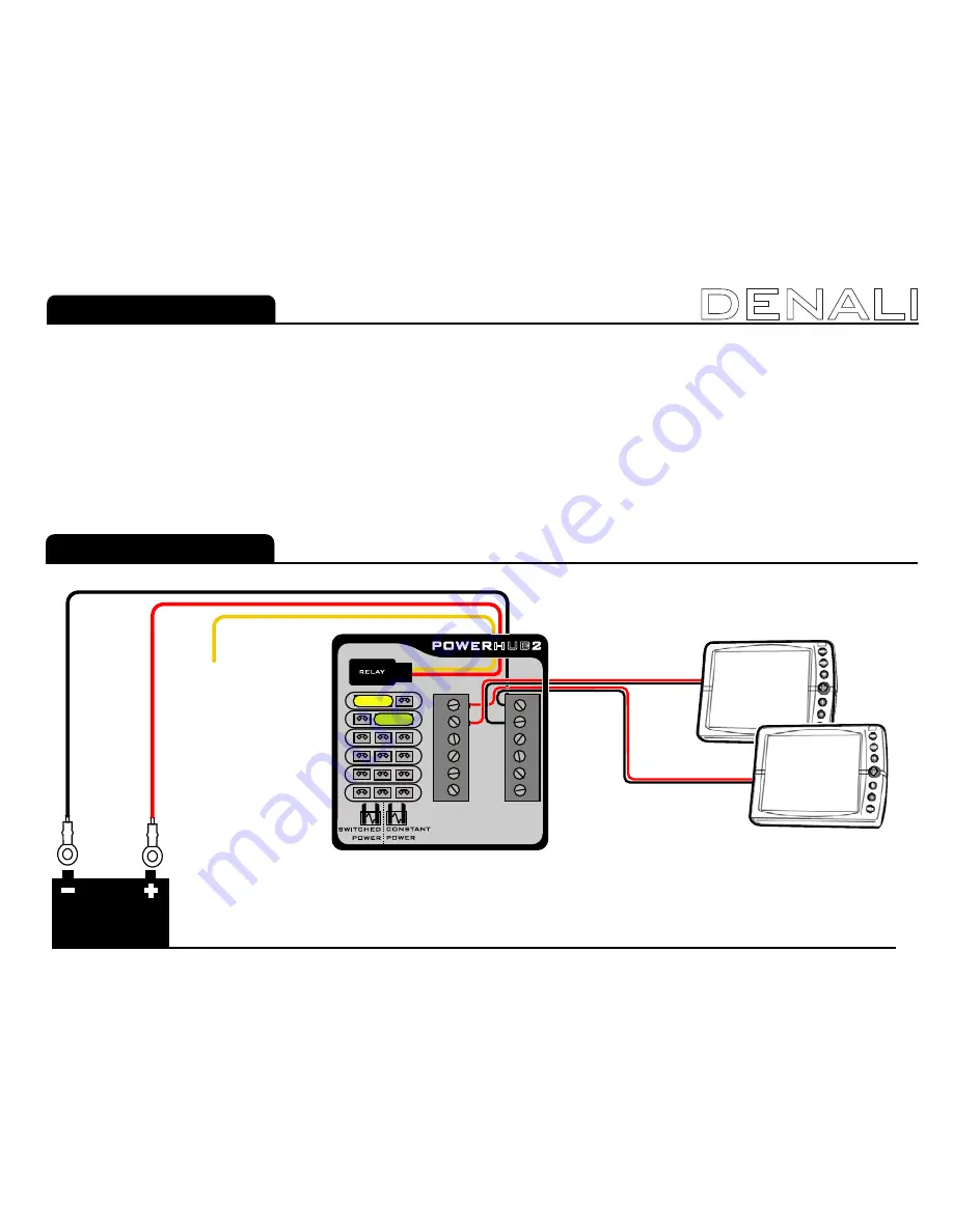
Wiring Diagram
(1) Connect the POWERHUB2 to your battery.
Start by connecting the red wire from the POWERHUB2 to the positive terminal of your battery. Connect the black wire from the POWERHUB2 to the negative terminal of your battery.
(2) Tap a switched power source on your motorcycle.
Use the “Posi-Tap” to tap the yellow wire to a switched 12V power source on your motorcycle. A switched power source is any wire that is +12 VDC when you motorcycle is turned on and 0 VDC when your
motorcycle is turned off. Refer to your service manual or local mechanic to find a suitable switched power source for you specific motorcycle. On BMW canbus motorcycles, use either the can bus adapter
(EC.02350, sold separately), or tap the original BMW power socket positive wire.
(3) Connecting your devices to the POWERHUB2.
Notice that the POWERHUB2 has 6 circuits. Each circuit has an output bus, ground bus, and 2 fuse positions. To connect a device, start by inserting the proper amperage Mini ATC fuse into either the
switched or constant fuse position in circuit 1. Then, connect the positive wire from your device to circuit 1 output terminal. Connect the ground wire from your device to the circuit 1 ground bus terminal on
the POWERHUB2.
Note:
The position of the fuse simply determines whether your device has power when the motorcycle is turned off. The switched fuse position will only allow power to the device when the motorcycle is turned on, while the constant fuse position will allow power to your
device even when the motorcycle is turned off.
1
Switched Example
2
DENALI
+12V DC Wire
123456
Switched
Constant
1
2
3
4
5
6
1
2
3
4
5
6
1
2
3
4
5
6
1
2
3
4
5
6
G
R
OUND
B
US
+12V OUTPUT
B
US


