background image

MULTI CHANNEL POWER AMPLIFIER

POA-3012CI

Owner’s Manual
Bedienungsanleitung

1.POA-3012CI_ENG.indd   1

2008/04/08   11:49:58

Summary of Contents for 3012CI - Power Amplifier

Page 1: ...MULTI CHANNEL POWER AMPLIFIER POA 3012CI Owner s Manual Bedienungsanleitung 1 POA 3012CI_ENG indd 1 2008 04 08 11 49 58...

Page 2: ...ng sollte auf keinen Fall durch das Abdecken der Bel ftungs ffnungen durch Gegenst nde wie beispielsweise Zeitungen Tischt cher Vorh nge o behindert werden Auf dem Ger t sollten keinerlei direkte Feue...

Page 3: ...ds EN60065 EN55013 EN55020 EN61000 3 2 and EN61000 3 3 Following the provisions of 2006 95 EC and 2004 108 EC Directive BEREINSTIMMUNGSERKL RUNG Wir erkl ren unter unserer Verantwortung da dieses Prod...

Page 4: ...e between the inside of the unit and the surroundings condensation dew may form on the operating parts inside the unit causing the unit not to operate properly If this happens let the unit sit for an...

Page 5: ...N STANDBY 17 w Power indicator 17 e Display 17 q Information display Displays present status information and Setup menu etc r ZONE select buttons 10 t ZONE operation mode indicators 6 13 y SETUP butto...

Page 6: ...or 8 w RS 232C connector 9 e Speaker terminals SPEAKER SYSTEMS 5 r AC inlet AC IN 10 t AUDIO INPUT connectors 7 y TRIGGER IN jacks 9 u MASTERTRIGGER OUT jack 9 i BUS INPUT connectors 7 o BUS OUTPUT co...

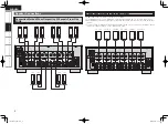
Page 7: ...some types of connections certain settings must be made on the POA 3012CI For details refer to the instructions for the respective connection items below Cables Used for Connections Select the cables...

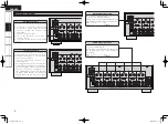
Page 8: ...RIDGED out putting a signal input to the AUDIO INPUT terminal input to an even numbered input terminal To select a signal for BRIDGED output from among the signals L R L R input to the BUS INPUT termi...

Page 9: ...pedance lower than specified for example 4 ohms speakers NORMAL MODE are used for an extended period of time with the volume turned up high the temperature may rise activating the protection circuit T...

Page 10: ...nel using INPUT SELECT on the Main Setup menu When BUS L R is used signals input to BUS INPUT L and R are mixed and output as monaural n When Using in NORMAL MODE To play signals input to the AUDIO IN...

Page 11: ...ble used a shielded twisted pair STP cable Do not use an unshielded twisted pair UTP cable as it may exceed noise standard limits For Europe model n Computer A computer with the following specificatio...

Page 12: ...vice If the trigger input level of the connected device is higher than 250 mA 12 V and depending on the short circuiting conditions the POA 3012CI s protection circuit may be activated in which case T...

Page 13: ...se the setting item of another ZONE is not displayed To configure the settings for DIMMER MODE and POWER CONFIGURATION use the SETUP button to select Main Setup mode 1Press the SETUP button The POA 30...

Page 14: ...ON vpage 14 Bright Dim Dark OFF POWER BUTTON ON LINE MASTER TRIGGER BTL AUX 2 BTL BUS L BTL BUS R BTL BUS L R BTL LCF OFF BTL LCF ON BRIDGED NORMAL CH 1 2 CH 3 4 CH 5 6 CH 7 8 CH 9 10 CH 11 12 CH 1 2...

Page 15: ...tup Option Setup vpage 15 vpage 15 vpage 15 vpage 16 IP Address Subnet Mask Default Gateway Primary DNS Secondary DNS Proxy Address Port Main Setup DHCP IP Address Mac Address DHCP ON OFF Address Name...

Page 16: ...see GSelectable ChannelsH in a VOLUME CONTROL Default NORMAL MODE Selectable Channels ON Low frequency component is cut OFF Low frequency component is not cut d LOW CUT FILTER Cuts the low frequency c...

Page 17: ...for about 3 seconds during the operation before reverting to the set brightness Selectable items POWER BUTTON Operate with the ON STANDBY button only ON LINE Operate from an external device via Ether...

Page 18: ...I performs automatic network setup due to the DHCP function When connecting to a network that has no DHCP function perform the setting in step 3 3Set the IP address at the menu Network Setup Network S...

Page 19: ...sional use only This function allows a DENON serviceperson or installer to check the POA 3012CI s status and make settings via the Internet NOTE Only use this function if so instructed by a DENON serv...

Page 20: ...Main Setup menu vpage 13 n To Switch Input Setting Refer to INPUT SELECT on the Main Setup menu vpage 13 Operating the POA 3012CI Using a Browser Web control This function lets you operate the POA 30...

Page 21: ...the web controller may be reset Resetting the Microprocessor Perform this procedure if the display is abnormal or if operations cannot be performed When the microprocessor is reset all the settings a...

Page 22: ...t securely Connect the speaker as required for the Operation Mode NORMAL MODE or BRIDGED MODE Connect the input connector correctly in the case of BRIDGED input for each ZONE input to an even numbered...

Page 23: ...20 1 POA 3012CI_ENG indd 23 2008 04 08 9 25 52...

Page 24: ...Denon Brand Company D M Holdings Inc Printed in Japan 00D 511 4719 004 www denon com 3 POA 3012CI_Backpage indd 1 2008 04 08 9 28 48...

Reviews: