Get
ting Star
ted
Connections
Set
up
Pla
ybac
k
Remot
e Contr
ol
Multi-Zone
Inf
or
mation
Tr
oubleshooting
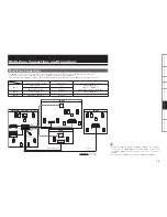
Multi-Zone Connections and Operations
Multi-Zone
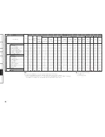
Connectors for audio output
Audio signals
Connectors for video output
ZONE2
ZONE2 PRE OUT
Stereo
ZONE2 VIDEO OUT,
ZONE2 S-VIDEO OUT,
ZONE2 COMPONENT VIDEO OUT
ZONE2 OPTICAL OUT
Bit-stream
ZONE3
ZONE3 PRE OUT
Stereo
ZONE3 VIDEO OUT
ZONE4
ZONE4 OPTICAL4 OUT
Bit-stream
–
Multi-Zone Connections
• For ZONE2, it is necessary to set in sequence with the signal connected to either the power amplifier or bit stream amps.
The amp should be the power amplifier in the case of ZONE3, and the bit-stream for ZONE4.
• If the signal inputted to ZONE2 is analog, change to PCM(2-channel) signal, and output it from ZONE2 optical output connectors.
$
'-
48
48
48
'3
4-
43
4#
3
4#
-
$
'-
'3
4-
43
$
'-
'3
4-
43
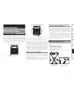
ZONE3 audio output
MAIN ZONE (7.1-channel system)
Monitor
ZONE2
ZONE3
DVD player
Input
Remote
control unit
ZONE2 audio
output
ZONE2 video
output
AVP-A1HD
Monitor
Power amplifier
: Video cable
: Audio cable
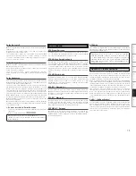
• When only using one speaker for ZONE2 or ZONE3, set to “Mono”.
In this case, the ZONE2 (ZONE3) monaural output is output from
the ZONE2 (ZONE3) pre-out L and R connectors, so connect as
desired.
• Separate power amplifiers are needed for ZONE2 and ZONE3.
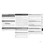
AV amplifier
ZONE4
ZONE4
digital output
Monitor
ZONE3 video
output
AV amplifier
Power amplifier
or
ZONE2 digital output
Power amplifier


