15
About the photos used for "descriptions of the DISASSEMBLY" section
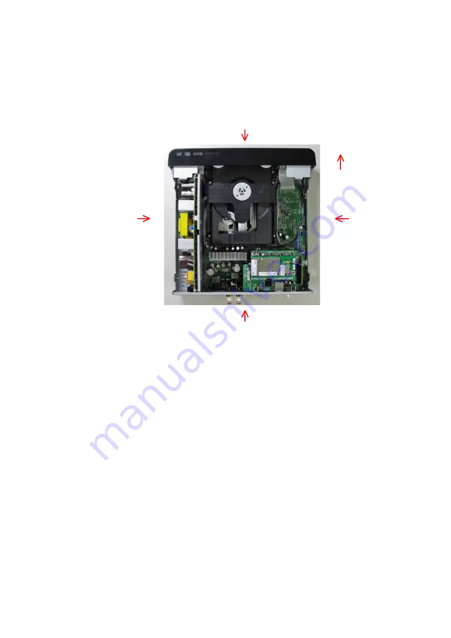
• The shooting direction of each photograph used herein is indicated on the left side of the respective photograph as
"Shooting direction: ***". (*** : A,B,C,D)
• Refer to the diagram below about the shooting direction of each photograph.
• Photographs with no shooting direction indicated
were taken from the top of the set.
• The photograph is RCD-N8(E2) model.
The viewpoint of each photograph
(Shooting direction)
[
View from the top
]
Front side
Shooting direction: A
Shooting direction: B
Shooting direction: D
Shooting direction: C
Summary of Contents for CEOL RCD-N8
Page 10: ...10 DIMENSION 299 0 112 0 108 0 35 0 35 0 210 0 280 0 2 0 301 0 218 0 45 0 36 0 30 0 4 0 ...
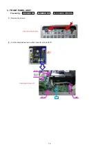
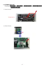
Page 22: ...22 3 Remove the screws 4 Remove the screws Shooting direction C Shooting direction A ...
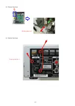
Page 24: ...24 4 Remove the screws remove the connector wires CN221 CN222 Shooting direction C ...
Page 84: ...84 PCM9211 MAIN IC103 ...
Page 85: ...85 PCM9211 Block Diagram ...
Page 86: ...86 PCM9211 Pin Discriptions ...
Page 87: ...87 NJM2755 MAIN IC701 NJM2755 Block Diagram ...
Page 93: ...93 L6565 SMPS IC821 L6565 Block Diagram ...
Page 94: ...94 ICE3BR1765J SMPS IC871 ICE3BR1765J Block Diagram ...


