background image

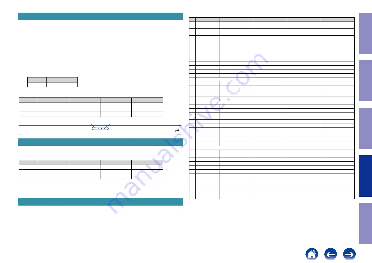
1. Version Display Mode

1.1. Actions

Version information is displayed when the device is started in this mode.

1.2. Starting up

(1-1)  for MTK Version : 

      While the power is On, hold down buttons "

SOURCE

", "

VOL-

" and "

VOL+

" for at least 5 seconds.

(1-2)  for MCK Version : 

      While the power is on, hold down buttons "

SOURCE

" and "

BT

" for at least 5 seconds.

(1-3)  for Region

      While the power is on, hold down buttons "

DIALOG ENHANCER LOW

" on the remote control for 

at least 10 seconds.

      LED1 blinks three times.  The region is displayed by the color of LED1.

Region

EU

LED1

blue

(2)  FIRMWARE version is displayed by LED.

  Example display

Version

LED1

LED2

LED3(

Blue

)

LED4(

Purple

)

01

non

non

Blinking x 0

Blinking x 1

10

non

non

Blinking x 1

Blinking x 0

24

non

non

Blinking x 2

Blinking x 4

2. Initialization Mode

1. While the power is On, hold down buttons "

RESET

" for at least 5 seconds.

(2)  All LEDs light up three times after initialization.

LED1

LED2

LED3

LED4

Step 1

Red

Red

Red

Red

Step 2

Red

Red

Red

Red

Step 3

Red

Red

Red

Red

(3)  Wait six seconds before turning on the power again.

3. Demo Mode

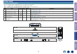
(1)  Demo Modes are ways to configure the sound bar with specific settings which are more desirable or 

even required for certain commercial retail point of sale installations.

(2)  You cannot go from one demo mode to another. You must exit the current demos.

(3) In demo mode, USB update will be canceled. In demo mode, reset command will be canceled.

Front side

LED1

LED4

Demo Mode Default Settings

#

Function

Default 1 Optical

Default 2 HDMI

Custom Demo Mode

Retail Display Mode

1 Start Demo Mode Press & hold [Source] and 

[Vol +] for 20 sec

Press & hold [Source] and 

[Vol +] for 23 sec

Press & hold [Source] and 

[Vol +] for 26 sec

Press & hold [Source] and 

[Vol +] for 29 sec

2 End Demo Mode

Press & hold [Source] and 

[Vol -] for 15 sec

Press & hold [Source] and 

[Vol -] for 15 sec

Press & hold [Source] and 

[Vol -] for 15 sec

Press & hold [Source] and 

[Vol -] for 15 sec

3 Save Demo Mode

N/A

N/A

Currently set system 

configuration captured and 

stored in memory for use 

when booting in "Custom 

Demo Mode" by pressing 

and holding the [Source] 

and [Vol -] for 5 sec.

N/A

4 Vol Default BT

12

12

12

12

5 Vol Default Other

16

16

16

26

6 Vol Min

0

0

0

26

7 Vol Max

31

31

31

26

8 Bass Adjust Default

6

6

6

6

#

Controls – Top Panel

9 Power

Disabled

Disabled

Disabled

Disabled

10 Vol Down

Enabled

Enabled

Enabled

Disabled

11 Vol Up

Enabled

Enabled

Enabled

Disabled

12 Source

Optical Only

HDMI Only

Enabled

Optical Only

13 Bluetooth

Enabled

Enabled

Enabled

Enabled

#

Control – IR Remote

14 Mute

Enabled

Enabled

Enabled

Enabled

15 Power

Disabled

Disabled

Disabled

Disabled

16 TV (HDMI ARC/

OPTICAL)

Enabled (Optical Only)

Enabled (HDMI Only)

Enabled

Enabled (Optical Only)

17 Bluetooth

Enabled

Enabled

Enabled

Enabled

18 Voice Adjust

Enabled

Enabled

Enabled

Enabled

19 Vol

Enabled

Enabled

Enabled

Disabled

20 Bass

Enabled

Enabled

Enabled

Enabled

21 Movie/Music 

modes

Enabled

Enabled

Enabled

Enabled

22 Night mode

Enabled

Enabled

Enabled

Enabled

#

Features Available

23 Bluetooth

Enabled

Enabled

Enabled

Enabled

24 HDMI ARC

Disabled

Enabled

Enabled

Disabled

25 HDMI CEC

Disabled

Enabled

Enabled

Disabled

27 Optical

Enabled

Disabled

Enabled

Enabled

24 AUX

Disabled

Disabled

Enabled

Disabled

28 Subwoofer

Enabled

Enabled

Enabled

Enabled

31 Movie Mode

Enabled

Enabled

Enabled

Enabled

32 Music Mode

Enabled

Enabled

Enabled

Enabled

33 Night Mode

Enabled

Enabled

Enabled

Enabled

34 Reset

Disabled

Disabled

Disabled

Disabled

35

Idle Reset Timer 

(No operation and 

no output)

120 sec

120 sec

120 sec

120 sec

55

 Before Servicing 

This Unit

 Electrical

 Mechanical

 Repair Information

 Updating

Summary of Contents for DHT-S416

Page 1: ...ure press release BEFORE SERVICING THIS UNIT ELECTRICAL MECHANICAL REPAIR INFORMATION UPDATING Ver 1 Confidential For purposes of improvement specifications and design are subject to change without no...

Page 2: ...ND OPTICS ONLINE PARTS LIST Accessing the Parts List Searching Part Numbers or Ref Numbers NOTE FOR PARTS LIST SERIAL NUMBER Serial Number Organization SKU Code of this Unit POST SERVICE PRECAUTIONS I...

Page 3: ...ic diagrams and parts lists be sure to use the designated parts Be sure to mount parts and arrange the wires as they were originally placed For safety seasons some parts use tapes tubes or other insul...

Page 4: ...NPUT CONDITION 4 CIRCUIT AND PARTS ARE SUBJECT TO CHANGE WITHOUT PRIOR NOTICE Electrostatic breakdown of the semi conductors or optical pickup may occur due to a potential differ ence caused by electr...

Page 5: ...9001 943203500730S DIODE RECTIFIER AXIAL CVD1N4007SL 1 2 SMPS D9002 943203500730S DIODE RECTIFIER AXIAL CVD1N4007SL 1 3 SMPS D9003 943203500730S DIODE RECTIFIER AXIAL CVD1N4007SL 1 4 SMPS D9004 943203...

Page 6: ...13 digit serial number that contains the code of the manufacturing plant and the manufacturing date Cumulative serial number SKU code Month 01 12 The last 2digit of year 13 digits SKU Code of this Un...

Page 7: ...ESET for at least 5 seconds 2 All LEDs light up three times after initialization LED1 LED2 LED3 LED4 Step 1 Red Red Red Red Step 2 Red Red Red Red Step 3 Red Red Red Red 3 Wait six seconds before turn...

Page 8: ...DMIC SCH17 Bar Module CONNECTOR SCH18 Bar SMPS SCH19 Subwoofer POWER AUDIO Power Supply SCH20 Subwoofer POWER AUDIO Wireless SCH21 Subwoofer Module AMP Circuit SCH22 Subwoofer Module AU PRINTED CIRCU...

Page 9: ...K 1 R13 100K U3 SY8120I BST 1 GND 2 FB 3 EN 4 VIN 5 SW 6 R1 0 0603 C10 22pF 50V NP0 R9 390K C12 10UF 6 3V X5R R5 100K NC 47uF 6 3V CE2 L3 2 2uH 2 1A R7 0 0402 R17 1K C16 10uF 10V X5R C13 10uF 25V X5R...

Page 10: ...8 PA7 17 PA11 32 PA10 31 PA9 30 PA8 29 PB15 28 PB14 27 PB13 26 PB12 25 PA12 33 PA13 34 VSS 35 VDDIO2 36 VDD 48 VSS 47 PB9 46 PB8 45 BOOT0 44 PB7 43 PB6 42 PB5 41 PB4 40 PB3 39 PA15 38 PA14 37 C21 10UF...

Page 11: ...49 100pF 50V NP0 C57 0 1uF 16V X7R C74 4 7uF 6 3V X5R R55 0 0402 C34 NC 10uF 10V X5R R36 4 7K R72 NC 0 R79 1K R42 10K R66 100K ESD1 ESD0402 2 1 R45 0 0402 C58 NC 10UF 6 3V R52 1K C51 100pF 50V NP0 C40...

Page 12: ...74LVC2G04DCKR 1A 1 GND 2 2A 3 2Y 4 VCC 5 1Y 6 C94 0 1uF 16V X7R C85 NC 10pF 50V NP0 R96 24 C86 0 1uF 16V X7R C152 1uF 10V X5R R98 10K C91 NC 10pF 50V NP0 FB8 220 500mA R95 10K C90 10pF 50V NP0 C89 100...

Page 13: ...D 15 CONFIG 16 OUT3B FFX3B 17 OUT3A FFX3A 18 EAPD OUT4B 19 TWARN OUT4A 20 VDD_DIG 21 GND_DIG 22 PWRDN 23 VDD_PLL 24 FILTER_PLL 25 GND_PLL 26 XTI 27 BICKI 28 LRCKI 29 SDI 30 RESET 31 INT_LINE 32 SDA 33...

Page 14: ..._CLK 19 GPIO8 15 GND 25 GPIO1 21 DSP_SPIO_MOSI 23 GPIO24 29 GPIO0 27 UTXD2 31 USB_DP_P0 40 GND 37 USB_DM_M1 39 USB_DP_P1 41 MRG_CLK_1 45 URXD2 46 GPIO10 49 HDMITX_SCL 56 HDMITX_HPG 58 I2S_8CH_BCK_1 65...

Page 15: ...2pF 50V NP0 R201 33 R324 0 NC C207 NC 10pF 50V NP0 TP1 R202 33 C205 NC 10pF 50V NP0 C206 NC 10pF 50V NP0 R214 NC 10K U1 IA3S4 GPIO17 12 EEWP GPIO3 11 SCL 10 SDA 9 VDD 8 USBN 7 USBP 6 GPIO14 4 GPIO25 3...

Page 16: ...16V X7R C307 100pF 50V NP0 C325 NC 33pF 50V NP0 R304 33 C301 10UF 6 3V X5R C323 NC 100pF 50V NP0 R311 0 0603 K3 TS 1302 2 1 3 4 C308 100pF 50V NP0 C326 NC 33pF 50V NP0 C322 NC 100pF 50V NP0 C311 2 2UF...

Page 17: ...NDK A25 GNDK A24 GNDK A2 GNDK F18 GNDK P12 GNDK P13 GNDK P14 GNDK P15 GNDK P18 GNDK R11 GNDK R13 GNDK R14 DVDD28_DPI AF15 VCCK_VPROC K19 GNDK U13 AVSS18_HDMITX AE21 DVDD28_NFI H25 AVDD18_HDMITX W19 GN...

Page 18: ...SDC0_DAT1 9 R29 5 1K_1 C94 NC 5 6pF 50V NP0 NC5 C47 NC 5 6pF 50V NP0 R42 33 1 2 MT8516SAOA U1E TCP N4 TCN N5 TDP0 P2 TDN0 P3 TDP1 R2 TDN1 R3 TDP2 T1 TDN2 T2 TDP3 T4 TDN3 T5 RCP M5 RCN M4 RDP0 K2 RDN0...

Page 19: ...CLKEN E3 RESETB J10 PWRKEY J9 PMU_TESTMODE K10 FSOURCE B6 INT A4 VBAT_VPROC D10 VBAT_LDOS2 L6 AVDD22_BUCK H10 VDIG18 A6 TYPEC_CC1 K1 TYPEC_CC2 K2 GND_VPROC E10 GND_VSYS H11 XIN A3 XOUT A2 GND_SPK C3 V...

Page 20: ...S0 D9 EDQS1 D7 EDQS2 C21 EDQS3 D19 EDQS0_B E9 EDQS1_B E7 EDQS2_B D21 EDQS3_B E19 ECLK0 E11 ECLK0_B D11 EA0 C12 EA1 A11 EA2 E15 EA3 B13 EA4 B11 EA5 A13 EA6 C11 EA7 D12 EA8 B10 EA9 A14 REXTDN C1 EA15 F1...

Page 21: ...VSS_CONN Y10 AVSS_CONN AA6 AVSS_CONN AB6 AVSS_CONN Y7 AVSS_CONN AA7 AVSS_CONN AB7 AVSS_CONN AC4 AVSS_CONN AA8 AVSS_CONN Y4 AVSS_CONN Y5 AVSS_CONN Y6 AVSS_CONN AB8 AVSS_CONN AA10 AVSS_CONN AB10 AVDD33_...

Page 22: ...B 1 EPAD 77 PDET0 66 PDET1 65 ANTSEL3 39 PCM_OUT 72 PCM_IN 71 AVDD13_WF_AFE 64 AVDD33_WF_A_TX 42 AVDD33_WF_A_PA 43 GPIO0 75 ANTSEL4 36 WF_RFIO_A 44 SDIO_DAT3 12 NC 2 DVDDIO 70 UART_RXD 73 UART_TXD 74...

Page 23: ...0 K7 NC_81 K10 NC_82 K12 NC_83 K13 NC_84 K14 NC_85 L1 NC_86 L2 NC_87 L3 NC_88 L12 NC_89 L13 NC_90 L14 NC_91 M1 NC_92 M2 NC_93 M3 NC_94 M7 NC_95 M8 NC_96 M9 NC_97 M10 NC_98 M11 NC_99 M12 NC_100 M13 NC_...

Page 24: ...X_HPG 11 C146 1uF 6 3V X5R 1uF 6 3V X5R R162 12K_1 0201 R NC11 NC MMD L1 4MIL 1 2 MT8516SAOA U1F BGA406 0 5 MT8167 HDMITX_CH0_M AD22 HDMITX_CH0_P AC22 HDMITX_CH1_M AE23 HDMITX_CH1_P AD23 HDMITX_CH2_M...

Page 25: ...GPIO24 GPIO66 4 GPIO51 4 GPIO50 4 KPROW0 I2S_8CH_LRCK_1 4 I2S_8CH_BCK_1 4 AD3 4 URXD0 4 UTXD0 4 UTXD2 4 URXD2 4 USB_DM_P0 4 USB_DP_P0 4 I2S_BCLK_TDM 10 I2S_DI_TDM 10 I2S_LRCK_TDM 10 GPIO66 10 I2S_BCK0...

Page 26: ...0 C8 4 7uF 25V R2 2 M D7 M7 C15 0 1uF 50V X7R CN2 6PIN 2 5mm 1 1 2 2 3 3 4 4 5 5 6 6 CX1 0 33uF 275VAC C9 2200pF 630V R26 120K U2 EL1018 1 2 4 3 Q1 G D S R24 TR2 100K D1 M7 LF1 FT15 13mH C13 2 7UF 50V...

Page 27: ...13 560K 5 C12 0 1uF 50V X7R C20 1uF 35V X5R R3 2 74M C11 270pF 50V NP0 R29 62 10uF 50V CE10 R18 33 Q1 G D S R38 100K R31 2 2K R4 2 74M R28 62 D4 BAS316 100V 0 5A M T1 SG8004 1 1 5 5 6 6 3 3 9 9 8 8 7...

Page 28: ...C618 10pF 50V NP0 M1 Moduel interface GPIO17 12 EEWP GPIO3 11 SCL 10 SDA 9 VDD 8 USBN 7 USBP 6 GPIO14 4 GPIO25 3 GPIO24 2 GPIO33 14 GPIO26 15 GPIO27 16 LRCK 17 DATA 18 SPI_CS 19 BCK 21 MCLK 22 GND 24...

Page 29: ...R C43 680pF 50V X7R C70 1000pF 50V X7R C45 0 1uF 50V X7R C56 1000pF 50V X7R XP8 2PIN 7 92mm 1 1 2 2 C54 4700pF 50V X7R C227 1000pF 50V X7R R55 10 R775 220K U6 STA369BW GND_SUB 1 SA 2 TEST_MODE 3 VSS 4...

Page 30: ...5 6 6 7 7 8 8 GND 9 GND 10 C925 10UF 6 3V X5R P3 5PIN CKX 3 5 29 M1 M1 M3 M3 M4 M4 M5 M5 M6 M6 R778 10 U12 DQR 012 DQR 012 OPTI 3 5V 1 GND 2 C957 NC 10pF 50V NP0 C958 100pF 50V NP0 R133 NC 10K 1 FB615...

Page 31: ...Y SMPS MAIN A side KEY A side AU_OPT A side AU_OPT B side KEY B side MAIN B side SMPS A side SMPS B side Lead free Solder When soldering use the Lead free Solder Sn Ag Cu 31 Before Servicing This Unit...

Page 32: ...For Subwoofer MAIN SUB MAIN SUB A side MAIN SUB B side 32 Before Servicing This Unit Electrical Mechanical Repair Information Updating...

Page 33: ...WIFI BT MT7668 other power signal Standard module New module Un standard module I2S IN_MRG WIFI KEY 1 HDMI OUT CEC ARC 5V_STB 3 3V_STB 3 9V_STB DC DC SY8120I DC DC SY8088 AMP_15V SW 5V_SYS SW 3 3V_SY...

Page 34: ...2C RST PDN FAULT 4 PBTL AMP STA369BW PVDD FOR AMP 3 3V_STB DC DC SY8213 18V POWER Board Wireless Module IA3S4 other power signal Standard module New module Un standard module 3V3 FOR AMP Wireless LED...

Page 35: ...85 VPROC_1 35V PMU MT6392 330mA 190mA 33mA 1mA 1mA WIFI_3 3V 100mA TLV62569 295mA VCore_1 15V 105mA 175mA 143mA 20mA 5V1 3V9 318mA 123mA VAUD28_PMU 1mA VAUD22_PMU 2mA VADC18_PMU VXO22_PMU VIO18_PMU VM...

Page 36: ...l IA3S4 SW OTHER LED 5 0mA MCU 2mA SY8120I 70 SY8088 70 VPROC_1 35V PMU MT6392 WIFI_3 3V TLV62569 VCore_1 15V 2 6mA 0mA 5V1 3V9 1 2mA 56mA VAUD28_PMU VAUD22_PMU VADC18_PMU VXO22_PMU VIO18_PMU VMC_PMU...

Page 37: ...I 70 SY8088 70 VPROC_1 35V PMU MT6392 WIFI_3 3V TLV62569 VCore_1 15V 2 6mA 0mA 5V1 3V9 1 2mA 12 6mA VAUD28_PMU VAUD22_PMU VADC18_PMU VXO22_PMU VIO18_PMU VMC_PMU I2S VUSB33_PMU VEMC_3V3 NAND I2S DDR_1...

Page 38: ...BW 85 5mA 7mA 2 45A 3V3 CURRENT DIAGRAM SUBWOOFER 18V 70mA 18V 50 8 3mA STB_5V for Wireless SY8213 70 STB_3V3 for LED SYS_3V3 for ST369BW 18V for ST369BW 5mA 7mA 1mA 3V3 18V 20mA CURRENT standby 82mA...

Page 39: ...SY8088I DC DC SY8120I POWER PCB 8P FFC 6P Wire 24P FFC wireless IA3S4 XP1 XP3 XP4 XP23 P2 P1 XP3 CN3 CN2 XP5 LED driver SN3112 4P Wire 4P Wire Power button BT button Source button Volume button Volum...

Page 40: ...r WIRING DIAGRAM for Subwoofer AM PCB AMP STA369BW Wireless Module IA3S4 CN1 XP8 2P AC JACK Subwoofer Pair button Pair LED SMPS DC DC TPS54202DDCR 40 Before Servicing This Unit Electrical Mechanical R...

Page 41: ...VER 2H POWER ON STANDBY 0 0 0 0 1 0 1 0 0 1 0 0 1 1 0 0 0 0 0 1 0 0 0 0 0 1 0 1 0 1 1 0 same as S316 10 Night SYSTEM 5H AMP RECIEVER 2H Night 0 0 0 0 1 0 1 0 0 1 0 0 1 0 1 1 0 1 0 1 0 0 0 0 0 0 0 1 0...

Page 42: ...SSY 2 PCB 3 SPEAKERS 4 POWER PCB for Subwoofer EXPLODED VIEW for Sound bar EXPLODED VIEW for Subwoofer SEALING GASKET VIEW OF AN AIR LEAK PREVENTION PACKAGING VIEW 42 Before Servicing This Unit Electr...

Page 43: ...BAFFLE ASSY DISASSEMBLY 1 BAFFLE ASSY and EXPLODED VIEW BAFFLE ASSY Ref No of EXPLODED VIEW 1 2 3 4 PCB DISASSEMBLY 2 PCB and EXPLODED VIEW AU_OPT PCB Ref No of EXPLODED VIEW 11 Main PCB Ref No of EXP...

Page 44: ...f each photograph for Subwoofer Shooting direction X View from the top Shooting direction C Shooting direction D Shooting direction A Shooting direction B Bottom Side Bottom Side Top Side Top Side Lch...

Page 45: ...REAR HOUSING BAFFLE ASSY CN3 XP5 XP1 BAFFLE ASSY PCB KEY PCB MAIN PCB POWER PCB AUX OPT Reuse this Heat sheet PCB MAIN Bside glue glue glue 3 SPEAKERS x4 x4 Lch Rch Proceeding POWER PCB for Subwoofer...

Page 46: ...ng assy 13 16 A D 1 2 3 4 5 6 7 8 9 10 11 12 13 14 15 16 17 19 20 21 22 23 24 25 26 27 28 29 30 31 32 32 34 35 WARNING Parts marked with this symbol z have critical characteristics Use ONLY replacemen...

Page 47: ...undunited com documents details 27546 CABINET ASS Y WITH SPEAKER 1 2 3 4 5 6 7 8 9 10 16 17 B C METAL REAR PANEL ASSY 12 13 2 13 14 15 16 3 17 18 1 10 11 12 6 5 7 4 8 9 20 19 47 Before Servicing This...

Page 48: ...1310S before use L 10 12MM 2 CUT_11 EVA L102 110 X W8 X T0 5MM Cut 919471101310S before use L 102 110MM 3 CUT_15 EVA L60 X W8 X T0 5MM Cut 919471101310S before use L 60MM 4 4 919471101160S EVA SHADING...

Page 49: ...soundunited com documents details 27546 1 4 9 7 5 6 20 21 10 13 12 11 5 14 17 15 16 18 19 27 22 23 2 3 28 29 Part A Part B mounting template QSG Safety notice 49 Before Servicing This Unit Electrical...

Page 50: ...ork 4 AUX IN cannot work 5 HDMI ARC cannot work 6 OPTICAL cannot work 7 SUB can not work 8 SUB is interrupted SPECIAL MODE Special mode setting button 1 Version Display Mode 2 Initialization Mode 3 De...

Page 51: ...PCB Yes or no Reconnect or use a new 24pin FFC cable instead NO 2 Keys do not work Reconnect or use a new 24pin FFC cable instead Replace the KEY PCB Replace the MAIN PCB Check the 24pin FFC cable an...

Page 52: ...EUT with a new one Replace the old MAIN PCB of the EUT with a new one Reconnect the antenna correctly If pin1 is defective replace U5 Replace the AU_OPT PCB YES YES YES YES NO NO NO YES Check that mod...

Page 53: ...e instead Replace the AU_OPT PCB Replace the FB9 NO YES NO 7 SUB can not work Replace the old MAIN SUB of the EUT with a new one YES YES Check that the wireless pairing LED is lit normally Yes or no C...

Page 54: ...ee 1 Version Display Mode 1 2 Version Display Mode for MCU SOURCE BT The firmware version is display See 1 Version Display Mode 1 3 Version Display Mode for Region DIALOG ENHANCER LOW Displays the reg...

Page 55: ...and Vol for 29 sec 2 End Demo Mode Press hold Source and Vol for 15 sec Press hold Source and Vol for 15 sec Press hold Source and Vol for 15 sec Press hold Source and Vol for 15 sec 3 Save Demo Mode...

Page 56: ...y Demo mode Retail Display Mode Source VOL Press Hold 29 sec Red Red Blinking 4 times on 0 5 sec Saving Demo mode for Custom Demo Mode Source VOL Press Hold 5 sec Green Green Blinking 3 times on 0 5 s...

Page 57: ...EDURE AFTER REPLACING THE U COM ETC FIRMWARE UPDATE PROCEDURE 1 Items necessary for update 2 Updating via Network 3 Updating via USB 57 Before Servicing This Unit Electrical Mechanical Repair Informat...

Page 58: ...The software has been written The software may need to be rewritten by version updates Check the version See FIRMWARE UPDATE PROCEDURE for information on writing the software C The software has not b...

Page 59: ...Equipment Not offered by D M Purchase from D M Article code Download from SDI Via OTA Smart phone X Internet Connection by broadband environment X Modem X Via USB USB flash drive USB 2 0 Min 1GB We r...

Page 60: ...phone Broadband Internet connection Modem 1 Search for Google Home in the App Store or Google Play and download the Home app for iOS or Android 2 Start the Google Home app 4 When an update is required...

Page 61: ...rough a hub Do not connect a computer to the USB port of this unit using a USB cable Do not use an extension cable when connecting the USB flash drive unit If a USB flash drive cannot be updated repla...

Page 62: ...2020 Sound United All Rights Reserved www denon com Before Servicing This Unit Electrical Mechanical Repair Information Updating...

Reviews: