background image

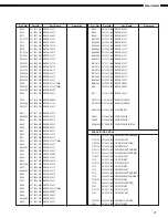
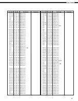
15

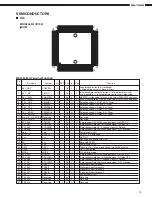
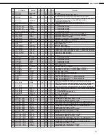
DN-780R

38

P37, A15

Reserved

I

0V

L

Not used.

39

P40, A16

PSCL

O

Pu

H

H

EEPROM communication clock signal.

40

P41, A17

PSDA

I/O

Pu

H

In

EEPROM communication data input¾and¾output signal.
(The input port of the time of a power supply injection is carried out.)

41

P42, A18

PSELEEP

I

Pd

L

L

EEPROM selection signal. L: Old EEPROM(X24C00)
H: New EEOPRM(S24C01)

42

P43, A19

PMIX

O

Pd

L

L

A mechanism line out. H: The mix output of A+B

43

V

SS

V

SS

GND(0V)

44

P44, AN4, A20

PKIN2

I

Lv

Pu

H

A / D conversion is used.

45

P45, AN5, A21

PREMO

I

Lv

Pu

H

A / D conversion is used.

46

P46, AN6, STOP, A22 PADINRB

I

Lv

Pd

L

A / D conversion is used.

47

P47, AN7, WDOUT, A23 PADINLB

I

Lv

Pd

L

A / D conversion is used.

48

P80, TM0IO

PRECR

I

Pu

H

Mechanism input signal. H: REC of RVS is improper.

49

P81, TM1IO

PRECF

I

Pu

H

Mechanism input signal. H: REC of FWD is improper.

50

P82, TM2IO

PHALH

I

Pu

H

Mechanism switch. H: No tape.

51

P83, TM3IO

PSWCOM

O

Pu

H

H

Mechanism scan signal. H: A mechanism selection

52

P84, TM4IO

PDUB

O

Pd

L

L

Duplicate output signal. H: Duplicate

53

P85, TM5IO

PRSVO4

O

0V

L

L

Preliminary output terminal 4

54

V

DD

V

DD

Power supply (+5V)

55

P86, TM6IOA

PRMTOUT

O

Pu

H

H

Remote output signal.

56

P87, TM6IOB

Reserved

I

0V

L

GND(0V) and connection.

57

P90, TM6IC

PQSENA

I

Pu

H

A mechanism leader tape detected signal. L: Leader tape detection.

58

P91, TM7IOA

PQSENB

I

Pu

H

B mechanism leader tape detected signal. L: Leader tape detection.

59

P92, TM7IOB

PRSVO1

O

0V

L

L

Preliminary output terminal 1

60

P93, TMI7IOC

PRSVO2

O

0V

L

L

Preliminary output terminal 2

61

V

SS

V

SS

GND(0V)

62

P94, AN0

PADINRA

I

Lv

Pd

L

A / D conversion is used

63

P95, AN1

PADINLA

I

Lv

Pd

L

A / D conversion is used

64

P96, AN2

PKIN0

I

Lv

Pu

H

A / D conversion is used

65

P97, AN3

PKIN1

I

Lv

Pu

H

A / D conversion is used

66

V

DD

(V

PP

)

V

DD

Power supply (+5V)

67

P70, SBT0

_PFLNCS

O

Pu

H

H

Connects with NCS. L: Select

68

P71, SBI0

RxD

I

Pu

H

It is used as a serial port. (It is 9615.38bps in 20MHz.)

69

P72, SBO0

TxD

O

Pu

H

H

It is used as a serial port. (It is 9615.38bps in 20MHz.)

70

P73, SBT1

PFLCLK

O

Pu

H

H

Connects with a clock.

71

P74, SBI1

PFLRD

I

Pu

H

Connects with SDO. (Key input data)

72

P75, SBO1

PFLSD

O

Pu

H

H

Connects with SDI

73

TEST1

TEST1

I

Pu

A pull-up is carried out by 47k. (Recommendation)

74

TEST2

TEST2

I

Pu

A pull-up is carried out by 47k. (Recommendation)

75

_NMI

_NMI

I

Pu

H

A pull-up is carried out.

76

PA0, _IRQ0

PPLSB

I

Ed

Pu

H

It counts by DOWN EDGE. It rotates one time at three counts.
(DN-770R was taken as one rotation by six pulses by both edge.)

77

PA1, _IRQ1

PPLSA

I

Ed

Pu

H

It counts by DOWN EDGE. It rotates one time at three counts.
(DN-770R was taken as one rotation by six pulses by both edge.)

78

PA2, _IRQ2

PPOFF

I

Pu

H

An electric-power-failure detected signal. L: Electric-power-failure detection.

79

PA3, _IRQ3

PEXTIN

I

Pu

H

EXT. IN input signal.

80

PA4, _IRQ4

PREMOTE

I

Ed

Pu

H

RC-5/Infrared remote signal input.

81

PA5, DSEP

PEXTOUT

O

Pu

H

H

EXT.OUT output signal.

82

_RST

_RESET

I

Lv

L

Reset signal. L: Reset

83

V

DD

V

DD

Power supply (+5V)s

84

P00, D00, AD00

PSOLHB

O

Pd

L

L

B mechanism solenoid hold signal. H: Hold

85

P01, D01, AD01

PSOLKB

O

Pd

L

L

B mechanism solenoid kick signal. H: kick

86

P02, D02, AD02

PRELRB

O

Pd

L

L

B mechanism reel motor inversion signal. H: Inversion signal ON.

87

P03, D03, AD03

PRELFB

O

Pd

L

L

B mechanism reel motor rotation signal.  H: rotation signal ON.

88

P04, D04, AD04

PCAPB

O

Pd

L

L

B mechanism capstan control signal. H: Capstan motor-on

89

P05, D05, AD05

PBIASB

O

Pd

L

L

B mechanism bias signal. H: Bias

90

P06, D06, AD06

PLMUTB

O

Pd

L

L

B mechanism line mute signal. L: Mute on

91

P07, D07, AD07

PHIGHB

O

Pd

L

H

High speed signal B mechanism. L: High

92

V

SS

V

SS

GND(0V)

93

P010, D08, AD08

PSOLHA

O

Pd

L

L

A mechanism solenoid hold signal. H: Hold

94

P011, D09, AD09

PSOLKA

O

Pd

L

L

A mechanism solenoid kick signal. H: kick

95

P012, D10, AD10

PRELRA

O

Pd

L

L

A mechanism reel motor inversion signal. H: Inversion signal ON.

96

P013, D11, AD11

PRELFA

O

Pd

L

L

A mechanism reel motor rotation signal. H rotation signal ON.

97

P014, D12, AD12

PCAPA

O

Pd

L

L

A mechanism capstan control signal. H: Capstan motor-on.

98

P015, D13, AD13

PBIASA

O

Pd

L

L

A mechanism bias signal. H: Bias

99

P016, D14, AD14

PLMUTA

O

Pd

L

L

A mechanism line mute signal. L: Mute on

100 P017, D15, AD15

PHIGHA

O

Pu

L

H

High speed signal A mechanism. L: High

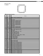
Pin Name

Function

Pin

No.

I/O

Symbol

DET Ext

Ini

Res

Summary of Contents for DN-780R

Page 1: ...NUAL MODEL DN 780R STEREO CASSETTE TAPE DECK Some illustrations using in this service manual are slightly different from the actual set 16 11 YUSHIMA 3 CHOME BUNKYOU KU TOKYO 113 0034 JAPAN Telephone...

Page 2: ...o double cassette deck Heads Recording playback head hard permalloy 2 Erase head Double gap ferrite 2 Motors Capstan DC servo motor 2 Reel DC motor 2 Tape Speed 4 8 cm sec Variable PLAY Approx 12 Fast...

Page 3: ...ront Panel 1 Remove 2 screws 4 and 3 screws 5 from top and bottom of the Front Panel 2 Disconnect the wire and 3 connectors from the Cassette Mecha then detach the Front Panel to the arrow direction 3...

Page 4: ...tte Mecha A and B 5 Cassette Door 1 Take off the Cassette Window on the front 2 Remove the screw to detach the Mini damper 3 Remove the screw to detach the Door Bracket 4 With pushing the shaft in the...

Page 5: ...W B disconnect the connector 2 Remove 3 screws 3 Remove 4 screws and each on the rear 7 Power P W B 1 Disconnect the power connector 2 Remove the screw and 4 screws 3 Release the P W B holder Power Co...

Page 6: ...6 DN 780R 4 3 2 1 5 6 7 8 D C B A E BLOCK DIAGRAM Option DN780R Block p65 02 06 27 16 04 Page 6 Adobe PageMaker 6 5J Win...

Page 7: ...0dB 50dB 60dB 70dB 20dB 40dB 30dB 0dB dBV IC103 403 HA12170 IC605 606 XLR 7 1 IC707 708 VR804 805 VR103 403 IC108 408 IC110 410 RCA 1 7 30 1 16 15 1 7 IC807 7 1 IC801 805 7 LINE IN MIC ACD 780 Option...

Page 8: ...0dB 30dB 0dB dBV 0dB 0 775V IC103 403 HA12170 XLR TR101 401 VR101 401 IC105 405 IC601 603 LOAD 600 ohm LOAD 33 ohm IC104 404 IC101 401 NJM2068 3 5 1 7 1 7 1 7 28 3 22 9 LINE OUT HEAD PHONE RCA ACD 780...

Page 9: ...etween 250 350g when the pinch roller starts to rotate Replace the pinch roller when it does not conform to the standard specification values 3 Replacing the Head Ass y 1 Removing the head Ass y 1 Rem...

Page 10: ...enuator 3 Electronic voltmeter 4 Oscilloscope 5 Frequency counter 6 Adjustment screwdriver 7 Trap coil adjustment square stick 8 Test tapes SONY TY 224 A BEX TCC 130 TCC 153 TCC 262B 162B TDK AC 514 9...

Page 11: ...Deck A and VR104 for Cassette Deck B 4 Playback System Adjustment 1 Playback level Playback a test tape for Dolby standard level A BEX TCC 130 Adjust Lch and Rch so that the LINE OUT terminal level is...

Page 12: ...signal and play this section back 2 Adjust Lch and Rch so that the output from LINE OUT terminal is the same as the output at recording monitoring time 5 3 Dolby C recording and playback comprehensiv...

Page 13: ...registered in this unit Check and refer to it when replacing the mechanism head or motor Ex The operating time of the Deck A mechanism The operating time of the Deck B mechanism Operating time unit ho...

Page 14: ...Pu H H B mechanism REC MUTE change signal H MUTE ON 14 P21 A01 PDOLOFB O Pd L L B mechanism Dolby on off change signal H Dolby OFF 15 P22 A02 PDOLBCB O Pu H H B mechanism Dolby B C change signal H Do...

Page 15: ...1 PFLRD I Pu H Connects with SDO Key input data 72 P75 SBO1 PFLSD O Pu H H Connects with SDI 73 TEST1 TEST1 I Pu A pull up is carried out by 47k Recommendation 74 TEST2 TEST2 I Pu A pull up is carried...

Page 16: ...ck oscillation output terminal 21 Vss I Power supply terminal Vss 0V 22 NCS I Chip select input L Serial input enable H Disable 23 SCK I Clock input for serial transference 24 SDI O Serial data input...

Page 17: ...VIEW Input GND Output FRONT VIEW Input GND Output m PC1297CA IC111 411 18 17 16 15 14 13 12 11 10 1 2 3 4 5 6 7 8 9 Vcc VR2 CIN R 2 PH2 CIN2 COUT2 VOUT21 VOUT22 VIN 0 VST VR1 VIN R 1 PH1 CIN1 COUT1 V...

Page 18: ...S KTC2875B l TRANSISTORS l DIODES LED DTA114EK DTA144EK DTC114EK DTC144EK DTC114EK R1 10kohm W R2 10kohm W DTC114ES 10kohm W 10kohm W GP1U271X Remote Control Sensor IC551 GND VCC VOUT Head Amp BPF In...

Page 19: ...ent 2 NP No pin 3 NX No extend pin 4 DL Datum line 5 1G 8G Grid NC pin should be electorically open on the PC board 1a 1a 1a 2a 1a 1a 1a 2a Dp2 Dp1 b f g e d c B6 B12 B1 B7 COLOR ILLUMINATION Reddish...

Page 20: ...1 1 1 1 1 2 24 25 12 9 1 1 6 5 15 12 1 12 1 12 1 1 2 16 17 12 1 17 1 5 1 2 16 17 1 1 9 10 1 1 6 6 7 1 1 4 1 2 COMPONENT SIDE PRINTED WIRING BOARD 8 7 6 5 4 3 2 1 A B C D E DN 780R 20 CONTROL POWER UN...

Page 21: ...5 8 1 4 5 8 1 4 5 8 1 4 5 8 1 4 5 8 1 8 9 16 1 4 5 8 1 4 5 8 1 4 5 8 1 4 5 8 1 8 9 16 1 25 26 50 51 75 76 100 1 11 12 22 23 33 34 44 FOIL SIDE 8 7 6 5 4 3 2 1 A B C D E DN 780R 21 CONTROL POWER UNIT A...

Page 22: ...3 1 3 12 1 12 1 12 1 12 1 12 1 12 1 12 1 1 3 1 3 12 1 15 1 9 10 18 1 3 1 9 10 18 1 15 16 30 1 15 16 30 1 12 1 12 1 12 1 12 1 15 1 2 24 25 COMPONENT SIDE 8 7 6 5 4 3 2 1 A B C D E DN 780R 22 AUDIO UNI...

Page 23: ...1 4 5 8 1 4 5 8 1 4 5 8 1 4 5 8 1 4 5 8 1 4 5 8 1 4 5 8 1 4 5 8 8 9 16 1 8 9 16 1 8 9 16 1 8 9 16 1 8 9 16 1 8 9 16 1 8 9 16 1 8 9 16 1 4 5 8 1 4 5 8 1 4 5 8 1 8 9 16 1 8 9 16 FOIL SIDE 8 7 6 5 4 3 2...

Page 24: ...1 15 1 4 5 8 1 4 5 8 1 4 5 8 1 4 5 8 1 4 5 8 1 4 5 8 1 8 9 16 1 8 9 16 COMPONENT SIDE FOIL SIDE 8 7 6 5 4 3 2 1 A B C D E DN 780R 24 GU 3463 XLR UNIT Ass y ACD 780 Option...

Page 25: ...always in stock and possibly to take a long period of time for supplying or in some case supplying of part may be refused l When ordering of part clearly indicate 1 and I i to avoid mis supplying l O...

Page 26: ...903 1SS355 TE 17 D907 918 276 0704 903 1SR35 400A T93X ZD101 102 276 0465 912 HZS7B 2TD ZD103 104 276 0457 904 HZS4C 1TD ZD105 108 276 0692 905 RD24SB T1 ZD901 276 0460 904 HZS5C 1TD ZD902 276 0463 90...

Page 27: ...970 RM73B 164JT R849 852 247 2011 942 RM73B 473JT R853 247 2009 983 RM73B 103JT Ref No Part No Part Name Remarks Ref No Part No Part Name Remarks R854 247 2015 948 RM73B 225KT R855 247 2011 942 RM73B...

Page 28: ...V 5 1 W101 203 0515 039 1P SIN CON CORD 1 W102 104 203 0605 033 1P SIN CON CORD 3 X101 399 0352 904 CSA20 0MXZ040 TF01 1 X301 399 0661 909 CSTS4 00MG06 1 461 0984 075 FL SPACER 2 C801 257 0504 982 CC7...

Page 29: ...5 2SK373 Y TPE2 TR403 406 273 0426 907 2SC2412KLNT146 TR407 408 269 0082 902 DTC114EKT96 TR409 412 273 0460 905 KTC2875B RTK TR413 269 0083 901 DTA114EKT96 TR414 415 269 0082 902 DTC114EKT96 TR416 269...

Page 30: ...247 2009 983 RM73B 103JT R457 458 247 2012 925 RM73B 104JT R459 462 247 2005 945 RM73B 151JT R463 467 247 2009 983 RM73B 103JT R123 124 247 2012 925 RM73B 104JT R127 128 247 2012 925 RM73B 104JT R129...

Page 31: ...577 247 2008 955 RM73B 302JT R578 579 247 2007 956 RM73B 112JT R580 581 247 2008 997 RM73B 432JT R582 583 247 2008 913 RM73B 202JT R584 247 2009 983 RM73B 103JT R585 247 2018 903 RM73B 0R0KT R701 704...

Page 32: ...21 424 254 4524 943 CE04W1H010MT SMG RE3 C425 426 255 1264 953 CQ93M1H272JT B C427 432 255 1264 940 CQ93M1H222JT B C433 434 254 4522 903 CE04W1V4R7MT SMG RE3 C435 438 254 4524 901 CE04W1H0R1MT SMG RE3...

Page 33: ...NIT ASS Y ACD 780 Option Ref No Part No Part Name Remarks SEMICONDUCTORS GROUP IC601 606 263 0565 007 BA15218 IC607 608 262 0707 901 TC4053BF TAPE RESISTORS GROUP R601 602 247 2018 903 RM73B 0R0KT R60...

Page 34: ...CC73CH1H101JT C621 624 257 0509 929 CK73B1H102KT C625 626 257 0502 926 CC73CH1H010CT C627 628 257 0503 925 CC73CH1H100DT C629 630 257 0502 926 CC73CH1H010CT C631 632 257 0503 925 CC73CH1H100DT C633 6...

Page 35: ...6 54 101 51 53 5 105 6 105 3 4 35 43 108 38 37 109 41 108 103 106 31 109 106 39 40 108 101 15 101 110 101 10 9 19 112 101 101 17 102 101 7 13 12 101 69 16 41 59 68 111 27 29 62 61 60 EXPLODED VIEW OF...

Page 36: ...013 6P KR KR CON CORD 1 37 412 3597 302 EJECT LEVER A 1 38 412 3599 009 LEVER STAY A 1 39 412 3598 301 EJECT LEVER B 1 40 412 3628 006 LEVER STAY B 1 41 463 8238 004 SPRING 2 42 338 0161 006 C MECHA...

Page 37: ...EXPLODED VIEW OF CASSETTE MECHANISM UNIT A 8 7 6 5 4 3 2 1 A B C D E DN 780R 37...

Page 38: ...F C39M 68 EJECT PREVENT ARM R 21 9DF C52H 13 CASSETTE HOLD SPRING 22 9DF C52F 16 SLIDE PLATE 23 9DF D45H 13 READ HOLDER 24 9DF D45G 13 PLAY ARM 25 9DF D45B 16 CAM GEAR 26 9DF D44T 14 REC DETECT LEVER...

Page 39: ...EXPLODED VIEW OF CASSETTE MECHANISM UNIT B 8 7 6 5 4 3 2 1 A B C D E DN 780R 39...

Page 40: ...H 13 CASSETTE HOLD SPRING 22 9DF C52F 16 SLIDE PLATE 23 9DF D45H 15 READ HOLDER 24 9DF D45G 13 PLAY ARM 25 9DF D45B 16 CAM GEAR 26 9DF D44T 14 REC DETECT LEVER 27 9DF D44Y 12 PACK DETECT LEVER R 28 9D...

Page 41: ...TICK LABEL E2 Model 1 203 505 0038 030 POLY COVER 1 204 511 3918 000 INST MANUAL 1 205 515 0923 003 S S LIST COM EX 1 206 203 2360 004 2P PIN CORD 4 207 505 8092 007 LAMINATE ENVELOPE 1 208 GEN0225 C...

Page 42: ...61 6 DISPLAY UNIT CW091 9P CY156 15P CX156 15P CY121 12P CX121 12P CY123 12P CX123 12P CY124 12P CX124 12P CY122 12P CX127 12P CY127 12P CX128 12P CX129 12P CY129 12P CX126 12P CY126 12P CY128 12P CY0...

Page 43: ...OR NOTICE WARNING Parts marked with this symbol have critical characteristics Use ONLY replacement parts recommended by the manufacture CAUTION Before returning the unit to the customer make sure you...

Page 44: ...PARTS ARE SUBJECT TO CHANGE WITHOUT PRIOR NOTICE WARNING Parts marked with this symbol have critical characteristics Use ONLY replacement parts recommended by the manufacture CAUTION Before returning...

Page 45: ...NOTICE WARNING Parts marked with this symbol have critical characteristics Use ONLY replacement parts recommended by the manufacture CAUTION Before returning the unit to the customer make sure you ma...

Page 46: ...e critical characteristics Use ONLY replacement parts recommended by the manufacture CAUTION Before returning the unit to the customer make sure you make either 1 a leakage current check or 2 a line t...

Page 47: ...E WITHOUT PRIOR NOTICE WARNING Parts marked with this symbol have critical characteristics Use ONLY replacement parts recommended by the manufacture CAUTION Before returning the unit to the customer m...

Page 48: ...R NOTICE WARNING Parts marked with this symbol have critical characteristics Use ONLY replacement parts recommended by the manufacture CAUTION Before returning the unit to the customer make sure you m...

Page 49: ...PRIOR NOTICE WARNING Parts marked with this symbol have critical characteristics Use ONLY replacement parts recommended by the manufacture CAUTION Before returning the unit to the customer make sure...

Page 50: ...Ver 1 00 1 page of 30 Specification for Serial Interface DN 780R Denon Ltd...

Page 51: ...T OF COMMAND CODES 9 1 7 LIST OF ANSWER CODES 10 1 8 LIST OF STATUS CODES 10 1 9 COMMAND SPECIFICATION 11 1 9 1 Reset 11 1 9 2 Request Play Status 12 1 9 3 Request CPU Version 13 1 9 4 Request Tape St...

Page 52: ...NC 8 NC 9 NC 1 2 Transfer format of serial data Interface RS 232C Communication system Half duplex communication Data transfer mode Start stop synchronization Transfer rate 9 600bps Start bit ST 1 bit...

Page 53: ...and code AC Answer Code Answer code PC Parameter Code Defined for each command contents and number of parameters ETX End of TeXt 03h BCC Block Check Character CC PC0 PC1 PC2 PCn ETX Xyh Each of X and...

Page 54: ...n b If the host has received NAK from this device it shall retransmit the command that it has transmitted immediately beforehand c When detect communication error such as overrun framing or parity err...

Page 55: ...e of this device a When a command is normally receivedand an answer is normally received with an answer parameter MAX 60ms Comand Transmitted CC PC0 PC1 PC2 PCn BCC STX ETX STX CC PC0 STX Answer Trans...

Page 56: ...hen a command is abnormally received with or without an answer parameter Command Transmitted CC PC0 PC1 PC2 PCn BCC STX ETX NAK CC PC0 STX NAK return Error Check NG Command Retransmitted HOST UNIT MAX...

Page 57: ...ived unit and an answer is abnormally received host Command Transmitted CC PC0 PC1 PC2 PCn BCC STX ETX STX NAK Answer Transmitted Error Check OK HOST UNIT AC PC0 PC1 PCn ETX BCC RC STX Answer Retransm...

Page 58: ...status 5 Request Establish 33h 3 Acquires the setup contents such as switch position and mode select 6 Request Machine ID 34h 4 Acquires the machine ID 7 Play 40h Starts playback or recording 8 Stop 4...

Page 59: ...he entire system 4Xh Status of A Mecha B Mecha No Status Code ASCII Description 1 Normal 31h 1 Normal mode 2 Twin REC 32h 2 Under twin recording 3 Dubbing 33h 3 Under dubbing 4 No Tape 41h A No casset...

Page 60: ...s and restarts same as power ON byte bit 7 6 5 4 3 2 1 0 0 STX 02h 1 Command code SP 2 Reserve 00h 3 Reserve 00h 4 Reserve 00h 5 Reserve 00h 6 ETX 03h 7 BCCH high level 8 BCCL low level a Answers retu...

Page 61: ...nter 1000 digit 0 1 2 8 9 8 A Mecha tape counter 100 digit 0 1 2 8 9 9 A Mecha tape counter 10 digit 0 1 2 8 9 10 A Mecha tape counter 1 digit 0 1 2 8 9 11 B Mecha status 12 Mark or 13 B Mecha tape co...

Page 62: ...00h 4 Reserve 00h 5 Reserve 00h 6 ETX 03h 7 BCCH high level 8 BCCL low level a Answers returned byte bit 7 6 5 4 3 2 1 0 0 STX 02h 1 Reply code 1 2 Answer code 3 CPU version No 1000 digit ASCII 4 CPU...

Page 63: ...returned byte bit 7 6 5 4 3 2 1 0 0 STX 02h 1 Reply code 2 2 Answer code 3 ETX 03h 4 A Mecha tape status 1 5 B Mecha tape status 1 6 BCCH high level 7 BCCL low level 1 Tape status CODE TAPE STATUS 30h...

Page 64: ...a Dolby 3 6 A Mecha Direction 4 7 A Mecha Memory 5 8 B Mecha Dolby 4 9 B Mecha Direction 5 10 B Mecha Memory 6 11 ETX 03h 12 BCCH high level 13 BCCL low level 1 DUPULICATE MODE 3 Dolby CODE DUPULICATE...

Page 65: ...02h 1 Command code 4 2 Reserve 00h 3 Reserve 00h 4 Reserve 00h 5 Reserve 00h 6 ETX 03h 7 BCCH high level 8 BCCL low level a Answers returned byte bit 7 6 5 4 3 2 1 0 0 STX 02h 1 Reply code 4 2 Answer...

Page 66: ...0h 5 Reserve 00h 6 ETX 03h 7 BCCH high level 8 BCCL low level a Answers returned byte bit 7 6 5 4 3 2 1 0 0 STX 02h 1 Reply code 2 Answer code 3 ETX 03h 4 BCCH high level 5 BCCL low level b Special co...

Page 67: ...1 3 Reserve 00h 4 Reserve 00h 5 Reserve 00h 6 ETX 03h 7 BCCH high level 8 BCCL low level a Answers returned byte bit 7 6 5 4 3 2 1 0 0 STX 02h 1 Reply code A 2 Answer code 3 ETX 03h 4 BCCH high level...

Page 68: ...Answer code 3 ETX 03h 4 BCCH high level 5 BCCL low level b Special conditions The device returns Condition Error status when mecha status data is No Tape 41h Play 43h Forward 47h Rewind 48h Cue 49h Re...

Page 69: ...serve 00h 4 Reserve 00h 5 Reserve 00h 6 ETX 03h 7 BCCH high level 8 BCCL low level a Answers returned byte bit 7 6 5 4 3 2 1 0 0 STX 02h 1 Reply code C 2 Answer code 3 ETX 03h 4 BCCH high level 5 BCCL...

Page 70: ...s returned byte bit 7 6 5 4 3 2 1 0 0 STX 02h 1 Reply code D 2 Answer code 3 ETX 03h 4 BCCH high level 5 BCCL low level b Special condition This command is not valid when system status is Twin REC 32h...

Page 71: ...turned byte bit 7 6 5 4 3 2 1 0 0 STX 02h 1 Reply code E 2 Answer code 3 ETX 03h 4 BCCH high level 5 BCCL low level b Special condition This command is not valid when system status is Twin REC 32h or...

Page 72: ...l 8 BCCL low level a Answers returned byte bit 7 6 5 4 3 2 1 0 0 STX 02h 1 Reply code F 2 Answer code 3 ETX 03h 4 BCCH high level 5 BCCL low level b Special condition This command is not valid when sy...

Page 73: ...nd code G 2 Deck mecha A Mecha 0 or B Mecha 1 3 ON OFF OFF 0 or ON 1 4 Reserve 00h 5 Reserve 00h 6 ETX 03h 7 BCCH high level 8 BCCL low level a Answers returned byte bit 7 6 5 4 3 2 1 0 0 STX 02h 1 Re...

Page 74: ...and code H 2 Deck mecha A Mecha 0 or B Mecha 1 3 Reserve 00h 4 Reserve 00h 5 Reserve 00h 6 ETX 03h 7 BCCH high level 8 BCCL low level a Answers returned byte bit 7 6 5 4 3 2 1 0 0 STX 02h 1 Reply code...

Page 75: ...ha 0 or B Mecha 1 3 Dolby 1 4 Reserve 00h 5 Reserve 00h 6 ETX 03h 7 BCCH high level 8 BCCH low level 1 Dolby Code Dolby 30h 0 OFF 31h 1 Type B 32h 2 Type C a Answers returned byte bit 7 6 5 4 3 2 1 0...

Page 76: ...status is Twin REC 32h or Dubbing 33h The answer code returns CONDITION ERROR This command is valid when A B both mecha status data is Stop 42h or REC Pause 44h The answer code returns CONDITION ERROR...

Page 77: ...level 1 Tape speed Code Tape speed 30h 0 Normal speed 31h 1 High speed x2 a Answers returned byte bit 7 6 5 4 3 2 1 0 0 STX 02h 1 Reply code K 2 Answer code 3 ETX 03h 4 BCCH high level 5 BCCH low lev...

Page 78: ...rmal speed 31h 1 High speed x2 b Answers returned byte bit 7 6 5 4 3 2 1 0 0 STX 02h 1 Reply code 5 2 Answer code 3 ETX 03h 4 BCCH high level 5 BCCH low level b Special condition This command is not v...

Page 79: ...mode 30h 0 Single 31h 1 Loop 32h 2 Relay 33h 3 Cascade a Answers returned byte bit 7 6 5 4 3 2 1 0 0 STX 02h 1 Reply code M 2 Answer code 3 ETX 03h 4 BCCH high level 5 BCCH low level b Special condit...

Reviews: