4
1
Serial Remote Control Terminal
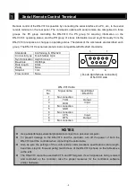
Remote control of the DN-V310 is possible by connecting the serial interface of a PC, etc., to the serial
remote terminal on the rear panel. The commands usable with serial remote are categorized in three
groups, the PC group controlling the DN-V310, the PS group for acquiring information on the
DN-V310’s operating status, and the PR group of status information issued asynchronously from the
DN-V310 in response to changes in operating status. The details of the commands are described each
group. The DN-V310’s serial remote terminal is compatible with RS-232C standards.
Pin
No.
Signal name
Input/Output
(
DN-V310
)
1
No connection
-
2
TXD
Output
3
RXD
Input
4
No connection
-
5
GND
-
6
No connection
-
7
CTS
Input
8
RTS
Output
9
No connection
-
Standards
Conforming to RS-232C
Connector type
D-sub female 9-pin
Synchronization Asynchronous
Baud rate
9,600 bps
Data length
8 bits
Parity
None
Stop bit
1 bit
Flow control
None
5
1
9
6
NOTES
Use a male/female serial straight cable to connect to a personal computer.
To prevent damage to the DN-V310 and the controller, turn off the power of both the
DN-V310 and the controller when connecting the serial cable.
Also be sure the settings of the control side’s communications specifications (data length,
baud rate, stop bit, flow and parity) match those of the DN-V310 (shown on the table above
at the left).
The DN-V310 cannot be used with CTS and RTS signals. If such signals are being received
and controlled on the controller, take the proper measures for the controller’s software
and/or hardware.
[ D-sub 9pin female connector ]
DN-V3
1
0 side
DN-V310 side

