DP-200USB
20
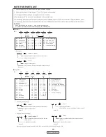
NOTE FOR PARTS LIST
Parts for which "nsp" is indicated on this table cannot be supplied.
When ordering of part, clearly indicate "1" and "I" (i) to avoid mis-supplying.
Ordering part without stating its part number can not be supplied.
Not including General-purpose Carbon Chip Resistor in the P.W.Board parts list. (Refer to the Schematic Diagram for those parts.)
Parts marked with this symbol
z
have critical characteristics.
Use ONLY replacement parts recommended by the manufacturer.
Not including General-purpose Carbon Film Resistor in the P.W.Board parts list. (Refer to the Schematic Diagram for those parts.)
Part indicated with the mark "
★
" is not illustrated in the exploded view.
WARNING:
1.
2.
3.
4.
5.
6.
●
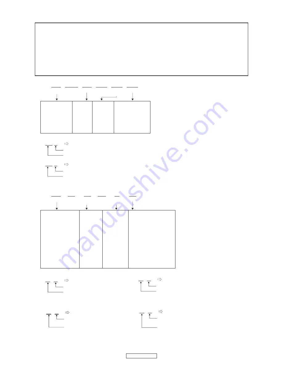
Resistors
RD : Carbon
RC : Composition
RS : Metal oxide film
RW: winding
RN : Metal film
RK : Metal mixture
P : Pulse-resistant type
NL : Low noise type
NB : Non-burning type
FR : Fuse-resistor
F : Lead wire forming
2B : 1/8 W
2E : 1/4 W
2H : 1/2 W
3A : 1 W
3D : 2 W
3F : 3 W
3H : 5 W
F :
±
1%
G :
±
2%
J :
±
5%
K :
±
10%
M :
±
20%
Ex.:
RN
Type
14K
Shape
and per-
formance
2E
Power
182
Resist-
ance
G
Allowable
error
FR
Others
*
Resistance
1800ohm=1.8kohm
1 8
2
Indicates number of zeros after effective number.
2-digit effective number.
1.2ohm
1 R
2
2-digit effective number, decimal point indicated by R.
1-digit effective number.
: Units: ohm
●
Capacitors
CE : Aluminum foil
electrolytic
CA : Aluminium solid
electrolytic
CS : Tantalum electrolytic
CQ : Film
CK : Ceramic
CC : Ceramic
CP : Oil
CM: Mica
CF : Metallized
CH : Metallized
HS : High stability type
BP : Non-polar type
HR : Ripple-resistant type
DL : For change and discharge
HF : For assuring high requency
U : UL part
C : CSA part
W : UL-CSA part
F : Lead wire forming
0J : 6.3 V
1A : 10 V
1C : 16 V
1E : 25 V
1V : 35 V
1H : 50 V
2A : 100 V
2B : 125 V
2C : 160 V
2D : 200 V
2E : 250 V
2H : 500 V
2J : 630 V
F :
±
1%
G :
±
2%
J :
±
5%
K :
±
10%
M :
±
20%
Z :
±
80%
: - 20%
P : +100%
C :
±
0.25pF
D :
±
0.5pF
= : Others
Ex.:
CE
Type
04W
Shape
and per-
formance
1H
Dielectric
strength
3R2
Capacity
M
Allowable
error
BP
Others
・
Units:
μ
F.
2200
μ
F
2 2
2
Indicates number of zeros after effective number.
2-digit effective number.
・
Units:
μ
F.
2.2
μ
F
2 R
2
2-digit effective number, decimal point indicated by R
1-digit effective number.
*
Capacity (electrolyte only)
・
When the dielectric strength is indicated in AC,"AC" is included after the dieelectric strength value.
*
Capacity (except electrolyte)
・
Units:pF
2200pF=0.0022
μ
F
2 2
2
Indicates number of zeros after efective number.
(More than 2)
2-digit effective number.
・
Units:pF
220pF
2 2
1
2-digit effective number.
Indicates number of zeros after effective numver.
(0 or 1)
Summary of Contents for DP-200USB
Page 4: ...DP 200USB DIMENSION ...
Page 5: ...DP 200USB WIRE ARRANGEMENT SW1 L e a f S W Leaf SW Sgnal wire AC cord ...
Page 7: ...DP 200USB BLOCK DIAGRAMS ...
Page 11: ...DP 200USB 10 DP 200USB 10 Terminal Function ...
Page 12: ...DP 200USB 11 DP 200USB 11 ...
Page 13: ...DP 200USB 12 DP 200USB 12 ...
Page 14: ...DP 200USB 13 DP 200USB 13 IS42S16100E 7TL IC203 ...
Page 15: ...DP 200USB 14 DP 200USB 14 ...
Page 16: ...DP 200USB 15 DP 200USB 15 SST39LF VF400A IC204 BLOCK DIAGRAM PIN FUNCTION ...
Page 17: ...DP 200USB 16 PRINTED WIRING BOARDS REC P W B UNIT 1 2 COMPONENT SIDE ...
Page 18: ...DP 200USB 17 REC P W B UNIT 2 2 FOIL SIDE ...
Page 19: ...DP 200USB 18 PH LI SPEED AC SW AC DC P W B UNIT 1 2 COMPONENT SIDE ...
Page 20: ...DP 200USB 19 PH LI SPEED AC SW AC DC P W B UNIT 2 2 FOIL SIDE ...
Page 27: ...DP 200USB 26 MEMO ...
Page 34: ...DP 200USB 33 MEMO ...
Page 37: ...12V 12V 12V 8 7 6 5 4 3 2 1 A B C D E F DP 200USB SCHEMATIC DIAGRAMS 2 3 ...
Page 38: ...8 7 6 5 4 3 2 1 A B C D E F DP 200USB SCHEMATIC DIAGRAMS 3 3 ...


