58
DVD-2910/955
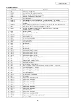
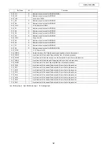
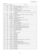
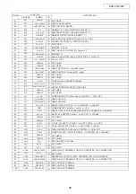
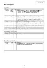
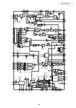
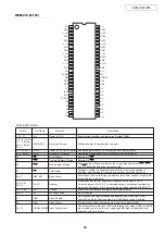
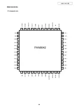
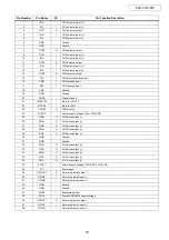
ADV7310 (IC701,710)
1
V
DD_IO
P
Digital power supply.
2~9, 12, 13
Y9-0
I
10-Bit Progressive scan/ HDTV input port for Y data.
10, 56
V
DD
P
Digital power supply.
11, 57
DGND
G
Digital Ground
14~18, 26~30
C9-0
I
10-Bit Progressive scan/ HDTV input port for CrCb color data in 4:2:2 input mode.
When this input pin is brought low, the ADV7300 interfaces over the SPI port and uses this
19
SPI/I2C
I
input as part of the 4 wire SPI interface. When this input pin is tied high [VDD_IO], the ADV7300
interfaces over the I2C port.
20
ALSB_SO
I/O
Multifunctional pin.
21
SDA_CLKSP
I/O
Multifunctional pin.
22
SCLK_SI
I
Multifunctional input.
23
P_HSYNC
I
Video Horizontal Sync Control Signal for HD sync in simultaneous SD/HD mode
and HD only mode.
24
P_VSYNC
I
Video Vertical Sync Control Signal for HD sync in simultaneous SD/HD mode
and HD only mode.
25
P_BLANK
I
Video Blanking Control Signal for HD sync in simultaneous SD/HD mode and HD only mode.
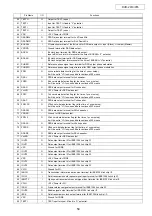
31
RTC_SCR_TR
I
Multifunctional input.
32
CLKIN_A
I
Pixel Clock Input for HD only or SD only modes.
33
RESET
I
This input resets the on-chip timing generator and sets the ADV7300 into Default Register
setting. Reset is an active low signal.
34
EXT_LF
I
External Loop filter for the internal PLL.
35, 47
R
SET1,2
I
A1520 Ohms resistor must be connected from this pin to AGND and is used to control the
amplitudes of the DAC outputs.
36,45
COMP
O
Compensation Pin for DACs.
37
DAC F
O
In SD only mode: Chroma/RED/V analog output.
In HD only mode and simultaneus HD/SD: Pb/ BLUE (HD) analog output.
38
DAC E
O
In SD only mode: Luma/BLUE/U analog output.
In HD only mode and simultaneus HD/SD: Pr/ RED (HD) analog output.
39
DAC D
O
In SD only mode: CVBS/GREEN/Y analog output.
In HD only mode and simultaneus HD/SD: Y/ GREEN (HD) analog output.
40
AGND
G
Analog Ground
41
V
AA
P
Analog power supply.
42
DAC C
O
Chroma/ RED/ V SD analog output.
43
DAC B
O
Luma/ BLUE/ U SD analog output.
44
DAC A
O
CVBS/ GREEN/ Y SD analog output.
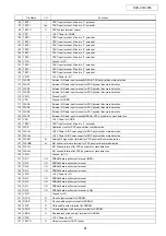
46
V
REF
I/O
Optional External Voltage Reference Input for DACs or Voltage Reference Output (1.235V).
48
S_BLANK
I/O
Video Blanking Control Signal for SD.
49
S_VSYNC
I/O
Video Vertical Sync Control Signal for SD.
50
S_HSYNC
I/O
Video Horizontal Control Signal for SD.
51~55, 58~62
S9-S0
I
10-Bit Standard Definition input port. Or Progressive Scan/ HDTV input port for
Cr [Red/V] color data in 4:4:4 input mode.
63
CLKIN_B
I
Pixel Clock Input.
64
GND_IO
G
Digital Ground
Function
I/O
Pin No.
Pin Name
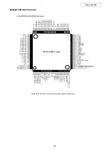
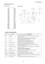
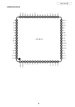
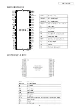
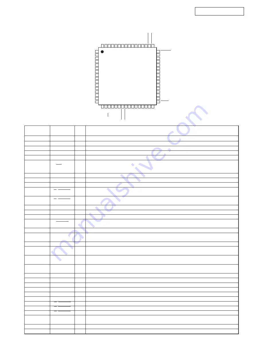
ADV7300 (MA: IC706)
1
2
3
4
5
6
7
8
9
10
11
12
13
14
15
16
48
47
46
45
44
43
42
41
40
39
38
37
36
35
34
33
17
18
19
20
21
22
23
24
25
26
27
28
29
30
31
32
64
63
62
61
60
59
58
57
56
55
54
53
52
51
50
49
VDD_IO
Y0
Y1
Y2
Y3
Y4
Y5
Y6
Y7
VDD
DGND
Y8
Y9
C0
C1
C2
C3
C4
ALSB
_SO
SD
A_CLKSP
SC
LK
_S
I
P_BLANK
C5
C6
C7
C8
C9
RTC_SCR_TR
CLKIN
_A
VREF
COMP1
DAC A
DAC B
DAC C
VAA
AGND
DAC D
DAC E
DAC F
COMP2
R
EXT_LF
SET 2
R
SET 1
GND_IO
CLKIN
_B
S9
S8
S7
S6
S5
DGND
VD
D
S4
S3
S2
S1
S0
SP
I/I2C
P_HS
YNC
P_VS
YNC
RESET
S_BLANK
S_VS
YNC
S_HS
YNC
TOP VIEW
ADV73
1
0
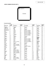
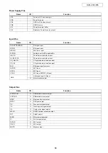
Terminal Function
Summary of Contents for DVD-2910
Page 29: ...29 DVD 2910 955 BLOCK DIAGRAM ...
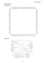
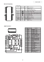
Page 48: ...48 DVD 2910 955 CXD2753R IC602 Pin Assignment Block Diagram ...
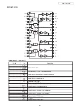
Page 79: ...79 DVD 2910 955 TA76432FC IC902 PC123 IC909 COLLECTOR EMITTER ANODE CATHODE TOP VIEW ...
Page 81: ...81 DVD 2910 955 PRINTED WIRING BORDS GU 3612 MAIN PWB P W B UNIT ASS Y COMPONENT SIDE ...
Page 82: ...82 DVD 2910 955 GU 3612 MAIN PWB P W B UNIT ASS Y FOIL SIDE ...
Page 83: ...83 DVD 2910 955 GU 3615 VODEO P W B UNIT ASS Y COMPONENT SIDE ...
Page 84: ...84 DVD 2910 955 GU 3615 VODEO P W B UNIT ASS Y FOIL SIDE ...
Page 85: ...85 DVD 2910 955 GU 3616 AUDIO POWER P W B UNIT ASS Y COMPONENT SIDE ...
Page 86: ...86 DVD 2910 955 GU 3616 AUDIO POWER P W B UNIT ASS Y FOIL SIDE ...
Page 117: ...DVD 2910 955 117 GU 3615 1 VIDEO P W B V6 V7 V8 V1 V2 V3 V4 V5 ...

