background image

MODEL

JP

E3

E2

EK

EA

E1 E1K E1C

HEOS Amp HS2

P P

Wireless Amplifier

Ver. 3

S0250V03DM/DG1804

• 

Please use this service manual with referring to the operating instructions without fail.

• 

Some illustrations using in this service manual are slightly different from the actual set.

• For purposes of improvement, specifications and design are subject to change without notice.

Please refer to the  

MODIFICATION NOTICE.

Copyright 2017-2018 D&M Holdings Inc. All rights reserved.

WARNING: Violators will be prosecuted to the maximum extent possible.

e

SERVICE MANUAL

e

D&M Holdings Inc.

Summary of Contents for HEOS Amp HS2

Page 1: ...ome illustrations using in this service manual are slightly different from the actual set For purposes of improvement specifications and design are subject to change without notice Please refer to the...

Page 2: ...region settings update procedures 20 4 Service Release Type settings update procedures 21 5 Firmware burning procedure after Core Module replacement flow 22 6 How to check the version Release Type Loc...

Page 3: ...you can do with this manual Search for a Ref No phrase Ctrl Shift F You can use the search function in Acrobat Reader to search for a Ref No in schematic diagrams printed wiring board diagrams block...

Page 4: ...Adobe Reader 9 On the Document menu click Sign Magnify schematic printed wiring board diagrams 1 Ctrl Space mouse operation Press Ctrl Space on the keyboard and drag the mouse to select the area you...

Page 5: ...en Example using Adobe Reader 9 On the Tools menu point to Select Zoom and then click Pan Zoom Window Magnify schematic printed wiring board diagrams 3 Loupe Tool function The Loupe Tool function lets...

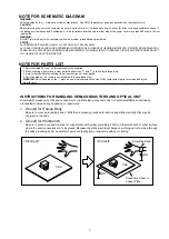
Page 6: ...tant safety parts that are indicated by the z mark on schematic diagrams and parts lists be sure to use the designated parts Be sure to mount parts and arrange the wires as they were originally placed...

Page 7: ...a part make a clear distinction between 1 and I i to avoid mis supplying 3 A part ordered without specifying its part number can not be supplied 4 Part indicated by mark is not illustrated in the expl...

Page 8: ...Personal notes 8...

Page 9: ...e 41 F 95 F 5 C 35 C Power supply AC 120V 60Hz for North America AC 220 240V 50 60Hz for Europe Power consumption 60W Power consumption in Quick Start Mode 4 5W Power consumption in Deep Standby mode...

Page 10: ...COVER See DISASSEMBLY 2 TOP COVER and EXPLODED VIEW TOP COVER ASSY Ref No of EXPLODED VIEW P3 BOTTOM COVER See DISASSEMBLY 3 BOTTOM COVER and EXPLODED VIEW COVER BOTTOM ASS Y Ref No of EXPLODED VIEW...

Page 11: ...dicate the shooting directions of photos The photographs with no shooting direction indicated were taken from the top of the unit Photos of HEOS AMP HS2 E2 are used in this manual The viewpoint of eac...

Page 12: ...Proceeding SIDE COVER 1 Remove the socket head cap screw Put the driver in the groove and push the side panel Use a 2mm tool bit or driver Remove the connector View from the bottom Shooting direction...

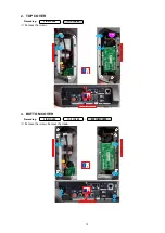
Page 13: ...the screws 3 BOTTOM COVER Proceeding SIDE COVER TOP COVER BOTTOM COVER 1 Remove the screws Remove the Hooks Shooting direction A Shooting direction D Shooting direction C x1 x5 BN13 Shooting direction...

Page 14: ...roceeding SIDE COVER TOP COVER BOTTOM COVER FRONT COVER DIGITAL ASSY 1 Remove the screws Remove the CONNECT PCB 2 Remove the screws Cut the wire clamp then remove the PCB HOLDER Shooting direction C A...

Page 15: ...6 MAIN ASSY Proceeding SIDE COVER TOP COVER BOTTOM COVER FRONT COVER DIGITAL ASSY MAIN ASSY 1 Remove the screws Shooting direction A View from the bottom x1 x7 x3 x2 15...

Page 16: ...been written The software is not written at the time of replacement B The software has been written The software may need to be rewritten by version updates Check the version C The software has not b...

Page 17: ...1 Download the Denon HEOS App Go to the App Store or to Google Play and search for HEOS by Denon to download and install 2 Launch the Denon HEOS App 3 If there is a software update follow step 1 to st...

Page 18: ...ve Save the update file on a blank USB flash drive for use If a USB flash drive cannot be updated replace it with a different USB flash drive and perform the update again 2 2 Unzipping the Downloaded...

Page 19: ...ing blue 5 Ready Configured and connected to your network Exsample of HEOS Link LED Actions 6 Be sure to rewrite the service region setting See 3 Service region settings update procedures Precautions...

Page 20: ...button 4 Input File name and Click Save button Note Typing the file name surrounded by double quotes No need file extention Model Area File name North America denon config locale set 1 Europe denon co...

Page 21: ...ad to start the notepad application 2 Enter TEXT 3 Click the File and Click the Save As button 4 Input File name aios config release type set 3 and Click Save button Note Typing the file name surround...

Page 22: ...y USB Remove the USB memory Automatically restart the system Change Region Setting Insert USB memory Writing See 3 Service region settings update procedures Remove the USB memory Power cycle Change Re...

Page 23: ...the following operation Step 1 Step 2 Step 3 Tap the My Devices Tap the HEOS3R Tap the Advanced Step 4 Step 5 Tap the About Check the version 2 How to check the version for HEOS Apps From Settings men...

Page 24: ...sed by the soldering of the PCB Check the damage of each part Replace the damaged part s Replace the IC91 ICE 3BR0665J and D912 D904 D905 D907 NO YES YES NO NO YES Repair the short circuited area s by...

Page 25: ...e in the rectifier circuit on the secondary side and check the circuit for short circuits Replace any faulty parts Replace the fuse after repair Check for short circuits between the regulator output t...

Page 26: ...y faulty parts Check the power 8VA 8V_A Check the control signal VOL_ DA VOL_CL during the power on settting Check the IC35 DAC 2 and IC31 PLD BLOCK Check digital signal DIR output digital data IC31 8...

Page 27: ...R output digital data IC31 85 86 87 88pin DAC2 intput digital data IC35 12 13 14 15pin Check analog signal DAC2 outtput analog data IC35 6 7pin Check the IC53 E Vol BLOCK Check input signal Analog sig...

Page 28: ...AUDIO CHECK PATH AUX IN LINE IN 28...

Page 29: ...OPT IN 29...

Page 30: ...This Phone Online music USB IN 30...

Page 31: ...EASY SETUP 31...

Page 32: ...MEASURING METHOD AND WAVEFORMS CUP12669Z 3 CONNECT PCB BD3473KS2 Control Signal R202 C225 R201 R207 C234 R208 R214 Q201 R213 C208 C211 C210 C214 C213 C205 w q BD3473KS2 Control Signal q DA w CL 32...

Page 33: ...08 L401 L402 D401 D403 D404 R105 R136 R194 R199 R350 R352 R353 R391 R392 R395 R413 R414 R420 R421 R424 R425 R426 R427 R432 R310 R164 R169 R170 R206 R209 R228 R229 R308 R351 R416 R418 R175 R176 R210 R1...

Page 34: ...Personal notes 34...

Page 35: ...IR4322 D AMP L R ch L R ch EASY SETUP TX TX2 nSS1 SPIMISO SPIMOSI SPICLK SPI_IRQ STBY_STATUS IR_DATAO USB ETHERNET FRONT LED REAR LED MUTE LED IC32 CS2100 FAULT CSD CLIP SP PROTECT SP PROTECT L R ch M...

Page 36: ...5V_A NJM2831F33 IC14 FTK943S IC96 5V_D 5V_ST IC25 EN53359QI IN CTL G OUT 3 3V_E 3 3V_D NJM2845DL118 IC33 1 8V_D Q930 19V 19V NJM2830V1 12 IC73 VCC Q901 PC92 PC91 IC93 ICE2QS02G 1 2 VCC 3 4 FB OLP 5 6...

Page 37: ...1 CN14 27PIN SOCKET 9PIN SOCKET CJP27HJ282Z CJP09HJ282Z LEGO MODULE VOLUME MUTE LED 3 COLOR LED 1 WIFI ANTENNA MCU UPDATE PLD UPDATE CN41 80PIN PIN HEADER 1 CN41 80PIN PIN HEADER CJP80GA369ZR 1 1 WIFI...

Page 38: ...784 R783 R536 R584 C530 C531 C532 C533 C534 R582 R517 R581 C564 C514 C550 C545 R535 C588 C586 C548 C546 C520 C561 C560 C513 C511 C510 R732 R731 R730 R703 R702 R701 JK72 JK71 R596 R725 R724 R708 R707 C...

Page 39: ...240 C239 C237 C235 C232 C216 C214 C211 C406 C134 C133 C132 C131 C130 C113 C150 C148 C149 C112 C144 C364 C349 C347 C137 C223 C202 C353 C301 C101 C238 C236 C231 C227 C217 C215 C210 C206 C405 C323 C321 C...

Page 40: ...10K R196 10K R198 0 R197 OPEN C127 OPEN R199 0 R202 0 C126 OPEN Q111 HVT2N3904SP C123 50V 0 1uF C124 50V 0 1uF 1 2 3 4 5 6 7 CN13 R141 10K R172 10K D111 1SS355 R174 8 2K R173 22K R176 100K Q113 RT1N1...

Page 41: ...0 41 42 43 44 45 46 47 48 IC22 PCM9211PTR R236 0 R238 OPEN R233 33 C229 OPEN C237 16V 0 1uF C232 16V 0 1uF R245 10K R244 10K R237 0 C222 10V 0 1uF C228 16V 0 1uF C226 16V 0 1uF C225 16V 0 1uF C224 16V...

Page 42: ...100 R314 100 R315 100 R346 10K R348 10K R347 10K C309 16V 0 1uF C311 16V 0 1uF C313 16V 0 1uF C315 16V 0 1uF C317 16V 0 1uF C319 16V 0 1uF C324 16V 0 1uF C302 16V 0 1uF C303 16V 0 1uF C306 16V 0 1uF C...

Page 43: ...G G S D Q407 CVTNTR4501NT1G G S D Q403 CVTNTR4501NT1G G S D Q404 CVTNTR4501NT1G G S D Q406 CVTNTR4501NT1G Q401 2SA1576A Q402 2SA1576A R497 100 R496 100 R495 100 R494 100 R493 100 R477 47K R478 47K R49...

Page 44: ...2SA1576 R537 4 7K R535 0 R539 150K C545 10 16V R526 100K R576 100K R563 0 R518 15K R568 12K C528 100pF D515 1SS355 C515 100pF R511 OPEN R505 47K L538 220R L537 220R L539 220R L540 220R L535 220R L536...

Page 45: ...m R747 10K D709 1SS355 C744 0 1uF D710 1SS355 R745 4 7 C739 1000pF C734 2200pF C735 2200pF R738 180 R733 47Kohm F R730 3 3K C731 100 50V R729 100K R732 3 3K C733 100 50V R731 OPEN C732 OPEN R734 0 R73...

Page 46: ...0 R835 180 1 2 3 4 5 BN57 CWB1B005050AA7 C831 0 1uF C833 0 1uF C832 0 1uF R840 10K R839 10K R838 10K 7 6 5 4 3 2 1 BN13 CJP07GB46ZY L811 220 L812 220 L813 220 L814 220 C813 50V 1000pF C812 50V 1000pF...

Page 47: ...3 Q922 RT1N141C R930 47 CX91 275V 224 K CY91 1000pF 400V CY92 1000pF 400V 1 2 3 4 LF91 CV630100SH 1 2 3 4 LF92 CV630100SH 1 2 HS92 1 2 HS93 CY93 NC R978 3K3F R958 15KF R957 15KF R956 15KF R955 0 ohm...

Page 48: ...2 C4 x3 S2 x2 S2 S1 S1 x2 x7 S2 x2 S6 S2 x6 P13 x6 C10 P15 x3 P18 x4 x2 S2 x3 S3 P17 P4 P4 2 1 P5 P5 2 1 P3 P3 2 1 P2 P2 1 3 x2 M7 C8 S2 x4 M11 x4 P2 2 x2 x4 S2 M10 x4 P19 P15 C7 P20 EXPLODED VIEW WAR...

Page 49: ...Personal notes Personal notes 49...

Page 50: ...Please refer to the last chapter for the part list 4 5 6 7 8 13 13 12 13 13 13 18 4 4 13 13 1 13 2 4 3 2 2 1 1 2 13 3 16 9 10 19 22 22 20 16 18 23 13 5 6 7 8 9 PACKING VIEW 50...

Page 51: ...78 G13 1 1 5 8 44 4368 4 XS 4 4368 4 XS 4 4368 4 4 4368 4368 4368 4 XS 4 4 4 4 4 308 6 90 836 6 28 66948 328630 6 1 436 0 328630 7 78 1 328630 6 7 8 4 0 4 74 32 4 37 00 836 6 4 6 4 8 4 8 4 6 4 8 4 7 0...

Page 52: ...SDA11 I VOLUP_BUTTON VOL button H Not pressed L Pressed 23 P51 INTP2 SO11 I VOLDOWN_ BUTTON VOL button H not pressed L Pressed 24 P17 TI02 TO02 TXD0 I CONNECT_ BUTTON Connect WPS button H Not pressed...

Page 53: ...22 ANI2 I Audio Power ON OFF Unused 40 P21 ANI1 AVREFM I Trigger cont Unused 41 P20 ANI0 AVREFP I JIG TACT SW Unused 42 P01 TO00 RxD1 I IR out FAULT Unused 43 P00 TI00 TxD1 I PLD_CS Unused 44 P120 ANI...

Page 54: ...sible maximum 18 single end with exclusion Low shock noise switching was realized by Micro Step Volume Zone 3 is possible Dual multi input selectors are built in 2 wire control copes with 3 3 5 V Appl...

Page 55: ...INR4 Rch input terminal 4 63 FLIN2 FLch input terminal for DVD 44 INL4 Lch input terminal 4 64 SRIN2 SRch input terminal for DVD 45 INR5 Rch input terminal 5 65 SLIN2 SLch input terminal for DVD 46 I...

Page 56: ...corporated Submit Documentation Feedback 7 Product Folder Link s PCM9211 Clock Data Recovery MPIO_A SELECTOR MPIO_C SELECTOR MPIO _B SELECTOR ADC Com Supply MPO0 1 SELECTOR MPO 0 MPO 1 MAIN OUTPUT SCK...

Page 57: ...I Yes Software control I F SPI chip select I2C slave address setting1 2 27 MODE I No Control mode setting see the Serial Control Mode section Control Mode Pin Setting 28 RXIN7 ADIN0 I Yes Biphase sign...

Page 58: ...PCM9211 Pin Discriptions 58...

Page 59: ...a bit clock input DIN 14 I Audio data input LRCK 15 I Audio data word clock input FMT 16 I Audio format selection I2 S Low Left justified High XSMT 17 I Soft mute control Soft mute Low soft un mute Hi...

Page 60: ...duction Clip and Fault reporting outputs High noise immunity RoHS compliant Typical Applications Home theatre systems Docking station audio systems PC audio systems Musical instruments Karaoke amplifi...

Page 61: ...14 VCC Low side supply 15 COM Low side supply return internally connected to pin 31 16 CSH1 CH1 High side over current sensing input referenced to VS1 17 VB1 CH1 High side floating supply 18 VS1 CH1...

Page 62: ...CHIP 1005 5 33ohm CRJ06IJ330T 1 R122 nsp RES CHIP 1005 5 47Kohm CRJ06IJ473T 1 R123 125 nsp RES CHIP 1005 5 33ohm CRJ06IJ330T 3 R126 nsp RES CHIP 1005 5 47Kohm CRJ06IJ473T 1 R127 nsp RES CHIP 1005 5 33...

Page 63: ...J10DJ332T 1 R818 nsp RES CHIP 1608 5 100Kohm CRJ10DJ104T 1 R819 nsp RES CHIP 1608 1 348Kohm CRJ10DF3483T 1 R820 nsp RES CHIP 1608 1 76 8Kohm CRJ10DF7682T 1 R821 nsp RES CHIP 1608 5 0ohm CRJ10DJ0R0T 1...

Page 64: ...44 346 nsp CAP CHIP 1005 16V 0 1uF X7R _SAMSUNG CCUI1C104KCS 3 C347 nsp CAP SMD ELECT 16V 47uF CCEC1CMVG470T 1 C348 nsp CAP CHIP 1005 50V 0 01uF X7R _SAMSUNG CCUI1H103KCS 1 C367 nsp CAP CHIP 1608 6 3V...

Page 65: ...9900 I C OPAMP DUAL LOW NOISE _Copper CVIAZ4580MTR E1 C 1 IC91 943231101950D I C SMPS CONTROLLER PG DIP 8 CVIICE3BR0665J 1 IC93 943239101570D I C PWM CONTROLLER PG DSO 8 CVIICE2QS02G 1 IC94 9432311018...

Page 66: ...5ohm CRJ14CJ750T 2 R752 nsp RES CHIP 1608 5 33Kohm CRJ10DJ333T 1 R753 nsp RES CHIP 1608 5 2 7Kohm CRJ10DJ272T 1 R754 nsp RES CHIP 1608 5 0ohm CRJ10DJ0R0T 1 R755 nsp RES CHIP 1608 5 4 7Kohm CRJ10DJ472T...

Page 67: ...NG CCUS1H101JAS 1 C517 nsp CAP SMD ELECT 50V 1uF CCEC1HMVG1R0T 1 C518 519 nsp CAP CHIP 1608 50V 2200pF X7R _SAMSUNG CCUS1H222KCS 2 C520 nsp CAP SMD ELECT 16V 22uF CCEC1CMVG220T 1 C521 nsp CAP CHIP 201...

Page 68: ...AH101T 2 C901 902 943134503130D CAP ELECT 470uF 250V 105 C 25 4X35 CCET250VTDA471N 2 C903 nsp CAP CHIP 2012 50V 0 47uF X7R _SAMSUNG CCUC1H474KCS 1 C904 nsp CAP CHIP 2012 50V 1uF X7R X7S _SAMSUNG CCUC1...

Page 69: ...nsp FERRITE CHIP BEAD 2012 220R CB05YTYH221 CLZ9R018V 1 L535 540 nsp FERRITE CHIP BEAD 2012 220R CB05YTYH221 CLZ9R018V 6 L551 nsp FERRITE CHIP BEAD 2012 220R CB05YTYH221 CLZ9R018V 1 L701 704 94311510...

Page 70: ...P2 3 FOOT VKL2A234 2 P3 943403101360S COVER TOP ASS Y VKD1A086WA 1 P3 1 TOP COVER VKD1A086R35G89 1 P3 2 TOP AIRVENT VKD1A087R35G89 1 P4 943404100850S SIDE ORNAMENT L ASS Y VGRHEOSAMPHS2L 1 P4 1 ORNAM...

Page 71: ...SHEET POLY SET VPP1A149Z 1 11 nsp TAPE ORANGE HEOS C4F3101OR 1 13 nsp INSTRUCTION MANUAL ASS Y E3 VQXHEOSAMPHS2S 1 13 nsp INSTRUCTION MANUAL ASS Y E2 VQXHEOSAMPHS2S 1 13 1 943539100940S BOX Accessory...

Reviews: