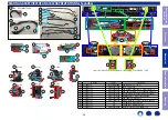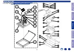
Explanatory Photos for DISASSEMBLY
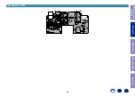
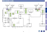
• For the shooting direction of each photos used in this manual, see the photo below.
•
A, B, C and D
in the photo below indicate the shooting directions of photos.
• The photographs with no shooting direction indicated were taken from the top of the unit.
• Photos of Heos Home Cinema HS2 are used in this manual.
The viewpoint of each photograph for SoundBar
(Shooting direction : X) [View from the top]
• Actual color of PRINTED CIRCUIT BOARDS may vary from those used in this manual.
The viewpoint of each photograph for SubWoofer
(Shooting direction:X)[View from the top]
↑
Shooting direction: A
↑
↓
Shooting direction: B
↓
↓
Shooting direction: D
↓
↓
Shooting direction: C
↓
C
C
Rch
Lch
Rch
Lch
↑
Shooting direction: A
↑
↑
Shooting direction: B
↑
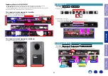
Proceeding :
GRILL ASSY
→
BAFFLE ASSY
(1) Remove the screws.
(2) Remove the connector.
Remove the green adhesive before unplugging the J15 connector.
• Actual color of PRINTED CIRCUIT BOARDS may vary from those used in this manual.
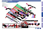
Proceeding :
GRILL ASSY
→
BAFFLE ASSY
→
MAIN and SMPS PCB
(1) Remove the screws. Remove the connector.
• Actual color of PRINTED CIRCUIT BOARDS may vary from those used in this manual.
1. BAFFLE ASSY
View from the Top
x4
x19
View from the Top
J13
J3
J11
J5
J15
2. MAIN and SMPS PCB
Glue x2
for E3/E2
for JP
Glue x2
x6
J1
J12 J9
J7
J4
CN1
2P
J2
SMPS PCB
MAIN PCB
Before Servicing
This Unit
Electrical
Mechanical
Repair Information
Updating
34


