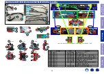
Proceeding :
GRILL ASSY
→
BAFFLE ASSY
→
MAIN and SMPS PCB
→
HDMI PCB
(1) Remove the screws.
(2) Remove the screws. Remove the Seal cap. Remove the connector.
• Actual color of PRINTED CIRCUIT BOARDS may vary from those used in this manual.
Proceeding :
GRILL ASSY
→
BAFFLE ASSY
→
MAIN and SMPS PCB
→
USB PCB
(1) Remove the screws. Remove the Seal cap. Remove the connector.
• Actual color of PRINTED CIRCUIT BOARDS may vary from those used in this manual.
3. HDMI PCB
View from the Rear
x2
View from the Front
x7
x1
J1
HDMI PCB
HDMI PCB
Seal cap
Seal cap
J1
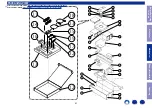
4. USB PCB
View from the Front
x4
J1
USB PCB
USB PCB Seal cap
J1
Proceeding :
GRILL ASSY
→
BAFFLE ASSY
→
MAIN and SMPS PCB
→
AC PCB
(1) Remove the screws. Remove the Seal cap. Remove the connector.
• Actual color of PRINTED CIRCUIT BOARDS may vary from those used in this manual.
Proceeding :
GRILL ASSY
→
BAFFLE ASSY
→
KEY PCB
See "
" for instructions on removing the KEY PCB.
Proceeding :
GRILL ASSY
→
BAFFLE ASSY
→
LED PCB
See "
" for instructions on removing the LED PCB.
5. AC PCB
View from the Front
x4
J1
AC PCB
AC PCB
Seal cap
J1
J4
6. KEY PCB
7. LED PCB
Before Servicing
This Unit
Electrical
Mechanical
Repair Information
Updating
35


