Proceeding :
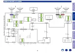
GRILL ASSY
→
WOOFER
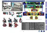
(1) Remove the screws. Remove the connector wire.
8. WOOFER for SubWoofer
↑
Shooting direction: A
↑
x12
BLK
RED
BLK
RED
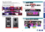
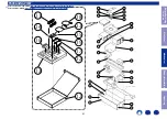
Proceeding :
GRILL ASSY
→
WOOFER
→
OPEN FRAME
(1) Remove the connector wire. Remove the PCB from the holder.
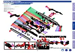
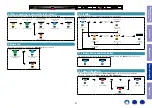
Proceeding :
GRILL ASSY
→
MAIM PCB
(1) Remove the screws.
(2) Remove the connector wire. Remove the screws.
9. OPEN FRAME for SubWoofer
↑
Shooting direction: A
↑
From AC IN
From MAIN PCB
978559100040D : Clip release jig : 1 Set
HOLDER
x 4
Insert Jig.
Pull up PWB.
10. MAIM PCB for SubWoofer
↑
Shooting direction: B
↑
↑
Shooting direction: B
↑
x8
Screw type T10
J1
J2
x4
for E3/E2
for JP
Before Servicing
This Unit
Electrical
Mechanical
Repair Information
Updating
36


