background image

D&M Holdings lnc.

e

Copyright 2011 D&M Holdings Inc. All rights reserved.

WARNING: Violators will be prosecuted to the maximum extent possible.

SERVICE MANUAL

INTEGRATED STEREO AMPLIFIER

MODEL

JP

E3

E2

EK

E2A E1C E1K EUT

PMA-710AE

3

3

Ver. 8

For purposes of improvement, specifications and design are subject to change without notice.

Please use this service manual with referring to the operating instructions without fail.

Some illustrations using in this service manual are slightly different from the actual set.

S0279-0V08DM/DG1105

Please refer to the

MODIFICATION NOTICE.

Summary of Contents for PMA-710AE

Page 1: ...ODEL JP E3 E2 EK E2A E1C E1K EUT PMA 710AE 3 3 Ver 8 For purposes of improvement specifications and design are subject to change without notice Please use this service manual with referring to the ope...

Page 2: ...ck that all screws parts and wires removed or discon nected for servicing have been put back in their original po sitions inspect that no parts around the area that has been serviced have been negativ...

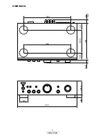
Page 3: ...3 PMA 710AE DIMENSION 344 434 60 102 5 20 265 20 5 23 max 50 5 165 5 49 344...

Page 4: ...perform adjustment or parts replacement etc be sure to rearrange them neatly as they were originally bundled or placed afterward Otherwise incorrect arrangement can be a cause of noise generation Wir...

Page 5: ...he photos were taken Photographs for which no direction is indicated were taken from above the product TOP CABINET FRONT PANEL ASSY POWER PCB REAR PANEL Refer to DISASSEMBLY 1 FRONT PANEL ASSY Refer t...

Page 6: ...style pins 3 Disconnect the connector wires then remove the screws Proceeding CABINET TOP FRONT PANEL ASSY View from bottom Style pin Loose cut CN52 CN53 CN95 CN92 CN94 CN50 CN55 CN51 CN93 CN94 Please...

Page 7: ...d in POWER PCB Proceeding TOP CABINET REAR PANEL Please refer to EXPLODED VIEW for the disassembly method in REAR PANEL Proceeding TOP CABINET REAR PANEL MAIN PCB ASSY Please refer to EXPLODED VIEW fo...

Page 8: ...44dB HEADPHONE 35 5dB MM VOLATAGE REGULATOR POWER AMP OUTPUT STAGE 16V 16V 16V PHONO EQ TONE POWER AMP FIRST STAGE CONTROL RELAY STANDBY 30dB 20dB 10dB 0dB 10dB 20dB 30dB 40dB 50dB 60dB 70dB CD etc 1...

Page 9: ...minals open do not connect the speakers dummy load etc 2 Adjustment 1 Remove top cover And then connect DC Voltmeter to the test points CN31 and CN32 of CUP12196B Main PCB 2 Connect power cord to AC w...

Page 10: ...tor LED lit red Check each connector The connectors are inserted completely Malfunction of RC71 or IC41 Power indicator LED remains flashing red and muting mode is not canceled protection mode is set...

Page 11: ...Is the fuse F901 normal Check the voltage of each department Check the operation of the switching relay switching IC and speaker relay Check the Signal line Power indicator LED is lit normally green...

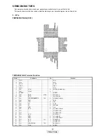
Page 12: ...UT X OUT 4 TEST TEST 5 VDD VDD 6 P21 XTIN O MUTE STANDBY LED 7 P22 XTOUT O 8 RESET I RESET 9 P20 INT5 STOP I STOP ACT 10 P00 INT0 I PROTECTOR 11 P01 PDO4 PWM4 PPG4 TC4 O P DIRECT RELAY 12 P02 RXD I RX...

Page 13: ...7 R S8 L COM1 L COM2 L COM3 ST VDD VSS R S1 R S2 R S3 R S4 R COM1 R S5 R S6 R COM2 R S8 R S7 DATA CK L S1 L S2 L S3 L S4 7 8 9 13 1 14 28 27 24 19 18 17 16 15 2 3 4 L S5 L S6 L S7 GND 20 21 22 23 25 2...

Page 14: ...14 PMA 710AE MEMO...

Page 15: ...15 PMA 710AE PRINTED WIRING BOARDS MAIN PCB ASSY 1 2 COMPONENT SIDE...

Page 16: ...16 PMA 710AE MAIN PCB ASSY 2 2 FOIL SIDE...

Page 17: ...17 PMA 710AE FRONT PCB ASSY 1 2 COMPONENT SIDE...

Page 18: ...18 PMA 710AE FRONT PCB ASSY 2 2 FOIL SIDE...

Page 19: ...ective number 2 digit effective number 1 2ohm 1 R 2 2 digit effective number decimal point indicated by R 1 digit effective number Units ohm Capacitors CE Aluminum foil electrolytic CA Aluminium solid...

Page 20: ...107804 TR KRC102M HVTKRC102MT 1 Q901 00D2720164004 TR KTD2058Y HVTKTD2058Y 1 Q902 00D2740202001 TR KTB1366Y HVTKTB1366Y 1 D215 216 00D9430182609 DIODE 1SS133 HVD1SS133MT 2 D221 222 00D9430182609 DIODE...

Page 21: ...2544703777 ELECT CAP RFS 50V 470MH4 CCEA1HRFSA470T 2 C325 326 nsp CERAMIC CAP 22PF 50V J CCCT1H220JC 2 C327 328 nsp CERAMIC CAP 1000PF 50V K CCKT1H102KB 2 C329 330 00D2544703777 ELECT CAP RFS 50V 470M...

Page 22: ...IN OUT CJJ4P028Z 4 JK31 00D9430191904 SPEAKER TERMINAL CJJ5Q006Z 1 L101 102 00D9430193601 TOROIDAL COIL CLU9S004Z 2 OL91 943641005850S AC OUTLET JACK 230V 3P E2 CJJ7A031Z 1 RY31 00D9430195103 RELAY G...

Page 23: ...0 2 D408 90M HD302310R ZENER DIODE MTZJ27B HVDMTZJ27BT 1 D409 943202005890S ZENER DIODE MTZJ9 1B HVDMTZJ9 1BT 1 D421 422 90M HD201840R RECTIFIER DIODE 1SR159 HVD1SR159 200 2 D458 90M HZ200190R SWITCHI...

Page 24: ...1 C591 nsp ELECT CAP 22uF 16V CCEA1CN220T 1 C592 nsp CHIP CAP 0 01uF 50V CCUS1H103KC 1 C595 nsp CHIP RES CRJ10DJ0R0T 1 OTHERS PARTS GROUP BK41 nsp PCB BRACKET CMD1A629 1 BK42 nsp PCB BRACKET CMD1A569...

Page 25: ...25 PMA 710AE MEMO...

Page 26: ...24 58 57 57 25 26 34 59 27 18 33 57 51 51 52 28 32 20 21 22 64 57 23 x3 x3 x3 x5 x2 x2 58 x3 57 x4 x2 65 x4 66 x4 x2 62 62 x4 63x9 60x2 61x6 x4 x4 x4 x2 x4 x4 54 x3 7 8 x5 55 x5 56 x2 57 9 z z z Parts...

Page 27: ...52 DENON BADGE SP CGB1A140T 1 8 00D9430179502 POWER KNOB BK CGK1A124ZA 1 8 00D9430179609 POWER KNOB SP CGK1A124YA 1 9 00D9430201505 PUSH KNOB BK CBC2A155B28 3 9 00D9430201602 PUSH KNOB SP CBC1A155RGG4...

Page 28: ...A155 42 nsp BUTYL TAPE W15 CMX1A189 43 nsp NITOFLON TAPE W15 CHS1A157 44 nsp NITOFLON TAPE W25 CHS1A158 45 nsp BUTYL TAPE W25 T2 CMX1A191 46 nsp NITOFLON TAPE W25 CHS1A158 47 nsp UL TUBE C4B120122 48...

Page 29: ...531006100D CARTON BOX E1C CPG2A818T 1 2 nsp POLY BAG Set CPB1A013Y 1 3 943533006080D SNOW PAD CPS2A747 2 4 1 943541006050D INSTRUCTION MANUAL E2 CQX1A1448Z 1 4 1 943541006060D INSTRUCTION MANUAL E1C C...

Page 30: ...7P BN51 BN52 7P 3P BN59 BN50 15P BN58 11P 15P CN50 CN93 3P 7P CN52 CN53 7P CUP12195 3 FUNCTION B D CUP12195 4 VOLUME B D 2P CN94 AC IN CN92 5P 2P 5P BN92 CN59 3P BN56 BN57 7P 7P CN56 CN57 7P 7P 7P BN5...

Page 31: ...31 PMA 710AE MEMO...
Page 32: ...check If the leakage current exceeds 0 5 milliamps or if the resistance from chassis to either side of the power cord is less than 460 kohms the unit is defective WARNING DO NOT return the unit to th...

Page 33: ...SIGNAL LINE 8 7 6 5 4 3 2 1 A B C D E F SCHEMATIC DIAGRAMS 1 2 CUP12196 1 MAIN Part CUP12196 2 Power Part s s PMA 710AE...

Page 34: ...SIGNAL LINE 8 7 6 5 4 3 2 1 A B C D E F PMA 710AE SCHEMATIC DIAGRAMS 2 2 CUP12195 1 Tone Part CUP12195 2 MCU Part CUP12195 3 Function SW Part CUP12195 4 Volume Part CUP12195 5 Power SW H P Part...

Reviews: