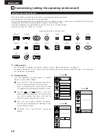
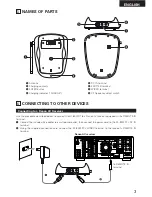
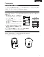
background image

3

ENGLISH

3

NAMES OF PARTS

q

Antenna

w

Charging contacts

e

ENTER button

r

Charging indicator (“CHARGE”)

4

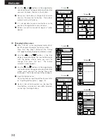
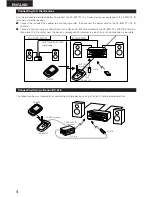
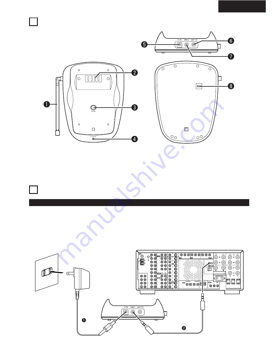
CONNECTING TO OTHER DEVICES

Connecting to a Denon AV Receiver

Use the procedure described below to connect the RC-8001ST to a Denon AV receiver equipped with a REMOTE IN
terminal.

q

Connect the included AC adapter to a wall power outlet, then connect the power cord to the RC-8001ST’s DC IN
terminal.

w

Using the supplied connection cord, connect the RC-8001ST’s WIRED terminal to the receiver’s REMOTE IN
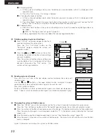
terminal.

t

DC IN terminal

y

EMITTER terminal

u

WIRED terminal

i

RF frequency select switch

R

L

OUT

OUT

OUT

OUT

OUT

OUT

PRE OUT

6    16
6    16

8    16

PHONO

FRONT

CENTER

EFECT
/ SB

SURROUND

SIGNAL
GND

CD

DVD

VDP

TV/  

DBS

V.AUX

VCR-1

VCR-2

MD/    

TAPE-1

TAPE-2

MONITOR

SOURCE

MULTI

OUT-1

MONITOR

OUT-2

DVD

VDP

TV/

DBS

V.AUX

VCR-1

VCR-2

VCR-1

VCR-2

VCR-1

VCR-2

MD/     

TAPE-1

TAPE-2

6CH EXT. IN

FR

SW

SR

ER

FL

C  

SL

EL

8CH EXT. IN

AUDIO

VIDEO

S-VIDEO

DIGITAL

SUB
WOOFER

R

L

R

L

R

L

Y

C

B

DVD

TV/DBS

COMPONENT VIDEO

SPEAKER SYSTEMS

OPTICAL

COAXIAL

OPTICAL-5

1

2

3

1

2

3

4

SWITCHED TOTAL 120W(1A.) MAX.

AC 120V   60Hz

AC OUTLETS

AC IN

FRONT

/ EFECT, SB

CENTER

R

L

R

L

SURROUND

SURROUND

POWER

AMP

REMOTE CONTROL 

FRONT / EFECT, SB / CENTER:
SURROUND / A OR B         :

A+B              :

MONITOR

ROOM TO ROOM
REMOTE
CONTROL

C

R

Y

C

B

C

R

Y

C

B

C

R

B

A

IN

IN

IN

IN

IN

IN

IN

IN

LOOP
ANT.

A M

FM

COAX.

75

ANTENNA TERMINALS

SB-R

SB/

SB-L

SB-R

SB / SB-L

To REMOTE IN 
terminal

Denon AV receiver

Summary of Contents for RC-8000

Page 1: ...T SERIAL NUMBER ATTACHED TO THE REAR OF THE CABINET FOR FUTURE REFERENCE NO DE SERIE PRIERE DE NOTER LE NUMERO DE SERIE DE L APPAREIL INSCRIT A L ARRIERE DU COFFRET DE FAÇON A POUVOIR LE CONSULTER EN CAS DE PROBLEME FOR ENGLISH READERS PAGE 42 PAGE 33 POUR LES LECTEURS FRANCAIS PAGE 34 PAGE 65 ...

Page 2: ...s 6 10 Preset Memory 10 17 1 Changing the preset memory of preset devices 12 2 Adding new devices 13 3 Operating devices for which the preset memory is set 14 17 Learning Function 18 19 1 Using the learning function 18 19 2 Inputting button names 19 System Call Function 20 22 1 System call buttons 20 2 Storing system call signals 20 21 3 Editing registered system call settings 21 22 4 Deleting reg...

Page 3: ...rection e Close the battery cover Notes on Batteries Use LR6 AA size alkaline batteries in the remote control unit The batteries should be replaced with new ones approximately once a year though this depends on the frequency of usage Even if less than a year has passed replace the batteries with new ones if the set does not operate even when the remote control unit is operated nearby the set The i...

Page 4: ...be adjusted so set Setting the liquid crystal display s auto off time and Setting the back light s auto off time to times that allow easy operation referring to page 23 and 24 2 Adjusting the brightness of the liquid crystal display Press the VOL up and ª down buttons while pressing the LIGHT button to adjust the brightness of the liquid crystal display The display gets denser when the VOL up butt...

Page 5: ...s or buttons are touched lightly operation is notified by a beep and the display of that part switches to a half tone dot mesh To turn off the beep refer to Making the sound settings on page 23 Use the procedure described below to display the device to be operated and its buttons q If the liquid crystal display is off either gently touch it or press the LIGHT button to turn it on w Press the JOG s...

Page 6: ...ion use the and buttons to display it Operating preset devices For details refer to the individual devices operating instructions To register devices not displayed by default or to change to brands other than those set by default add the device using the procedure described in section Preset Memory on page 10 For instructions on editing sorting or deleting the icon display section also refer to Ad...

Page 7: ...te control codes are sent When the CURSOR PAGE button is pressed again the display returns to normal and the mode switches back to the normal page operation mode The CURSOR PAGE button can be operated when an AV amplifier DVD player or DBS receiver is selected 2 DENON TUNER system buttons The transmission codes of independent buttons are the same as for AV AMP 2 TV system buttons The default setti...

Page 8: ...f AV amplifier VOLª Main volume of AV amplifier MUTE Muting of AV amplifier Transmission codes of independent buttons CH VCR channel CHª VCR channel VOL Main volume of AV amplifier VOLª Main volume of AV amplifier MUTE Muting of AV amplifier The default setting is HITACHI 1 To change the specified brand refer to Changing the preset memory of preset devices on page 12 ...

Page 9: ...m buttons Transmission codes of independent buttons VOL Main volume of AV amplifier VOLª Main volume of AV amplifier MUTE Muting of AV amplifier 2 DENON CDR CD recorder system buttons The transmission codes of independent buttons are the same as for CD ...

Page 10: ...preset in the RC 8000 it can be operated from the RC 8000 using the preset memory Note that some devices and some buttons may not be operable If this is not the case use the learning function see page 18 to store the device s remote control signals in the RC 8000 Depending on the product response may be slow If this is the case buttons may operate if they are pressed for a little longer than usual...

Page 11: ...SANYO 1 to 4 SHARP 1 to 3 SONY 1 to 3 SYLVANIA 1 TOSHIBA 1 to 3 DENON 1 2 PANASONIC 1 PIONEER 1 to 3 RCA 1 SONY 1 TOSHIBA 1 to 4 HITACHI 1 to 4 JVC 1 to 5 MAGNAVOX 1 to 4 MITSUBISHI 1 to 6 PANASONIC 1 to 5 PHILIPS 1 to 4 GE 1 2 PIONEER 1 to 4 PROSCAN 1 RCA 1 to 7 SANYO 1 2 SHARP 1 to 4 SONY 1 TOSHIBA 1 to 4 DENON 1 DENON 1 DENON 1 DENON 1 DENON 1 11 ENGLISH AVAMP TUNER TV DVD VCR MD DAT RCVR AIR O...

Page 12: ...de number from the code list The transmission test screen e appears e Press the ON OFF button on the transmission test screen to check the operation of the device If the code is right the power of the device you are attempting to operate should turn on and off If the device has operated press the OK button to select that preset memory If the device has not operated press the Cancel button and try ...

Page 13: ... e appears e Press the ON OFF button on the transmission test screen to check the operation of the device If the code is right the power of the device you are attempting to operate should turn on and off If the device has operated press the OK button to select that preset memory If the device has not operated press the Cancel button and try a different code If the desired preset code is not listed...

Page 14: ... names for buttons at which no transmission codes are set are displayed in gray characters No transmission codes are set for buttons which do not have button names NOTES The signals registered at the buttons the presence or absence of transmission codes depend on the preset code which has been set If the contrast is strong it may be difficult to read gray characters If this is the case adjust the ...

Page 15: ... VCR channel CHª VCR channel VOL Main volume of AV amplifier VOLª Main volume of AV amplifier MUTE Muting of AV amplifier 2 CD CD player and CD changer preset memory buttons Transmission codes of independent buttons VOL Main volume of AV amplifier VOLª Main volume of AV amplifier MUTE Muting of AV amplifier ...

Page 16: ...s 2 VDP video disc player preset memory buttons 2 DBS satellite preset memory buttons Transmission codes of independent buttons CH DBS channel CHª DBS channel VOL Main volume of AV amplifier VOLª Main volume of AV amplifier MUTE Muting of AV amplifier ...

Page 17: ...e of AV amplifier MUTE Muting of AV amplifier 2 LIGHT preset memory buttons A UTILITY page is added at the last page for the device Buttons can be added to this page using the learning function Refer to the instructions on using the learning function in section to learn buttons Refer to page 18 for details The transmission codes of independent buttons are the same as for CD ...

Page 18: ...reen Press the Key Learning button on the Setup 2 4 page to display the device selection screen w Press the icon in the icon display section for the device whose button s you want to learn to display the button selection screen e Use the and buttons in the page display section to display the page on which the button you want to learn is displayed Point the source remote control towards the RC 8000...

Page 19: ...ist of labels at the label selection screen Key Label to display the button name you wish to input from among the preset button names preset labels b Press the button name you wish to input That button is displayed with a half tone dot mesh Now press the OK button to set that button name w Inputting characters manually a To input a button name other than the preset labels use the and buttons on th...

Page 20: ...call signals as an example Settings Turn on AV amplifier power Switch AV amplifier input to DVD Turn on DVD player power Set DVD player to play mode q Press SETUP on the icon display section for 3 seconds to display the setup screen Press the Sys Call Setup button on the Setup 3 4 page to display the system call selection screen w Press the Add button on the system call selection screen to set the...

Page 21: ...tion for 3 seconds to display the setup screen Press the Sys Call Setup button on the Setup 3 4 page to display the system call selection screen w Press the and buttons on the call list to display the system call button you want to edit Press the system call button you want to edit so that it is displayed in half tone dot mesh then press the EDIT button to set the system call edit mode e Editing s...

Page 22: ...ose settings you want to delete so that it is displayed in half tone dot mesh then press the Del button The system call setting is deleted Screen q Screen w 5 Sending system call signals Press the Sys Call icon in the icon display section to display the system call sending screen Use the and buttons in the page display section to display the page containing the system call button whose signals you...

Page 23: ... to OFF no sound is produced when buttons are pressed Press the SETUP icon in the icon display section for at least 3 seconds to display the setup screen Press the Sound ON button on the Setup 4 4 page to switch the setting to OFF The display changes each time the button is pressed The displayed setting is the current setting 3 Setting the liquid crystal display s auto off time With the RC 8000 th...

Page 24: ...ven when the LIGHT button is pressed It is not possible to set the back light auto off time to a time longer than the liquid crystal display s auto off time When performing the system setup procedure for Denon AV receivers set the LCD s auto off time to a long time before operating Resetting The reset function resets all the settings to the factory defaults a Press SETUP in the icon display sectio...

Page 25: ...e the learning function to store their signals NOTE For AIR air conditioner some air conditioner remote control signals include time and temperature data sent along with the control codes so they may not work properly when they are learned in the RC 8000 OTHER REGISTERABLE DEVICES 5 2 PROJECTOR 2 HOME 2 AIR 2 OTHER ...

Page 26: ...ices For instructions on adding new devices refer to section Adding new devices on page 13 For types of devices for which there is no preset memory the preset memory selection screen is not displayed but the device can be added 2 Deleting devices Use the procedure described below to delete devices that have been added q Press SETUP in the icon display section for at least 3 seconds to display the ...

Page 27: ...splay the setup screen Press the Move Device button on the Setup 1 4 page to display the device selection screen w Use the and buttons in the icon display section to display the icon for the device you want to move then press that icon e Press the icon at the position to which you want to move the first icon A confirmation screen appears Press the Yes button The first icon is inserted at the posit...

Page 28: ...o display the icon for the device for which you want to register a device name etc then press that icon e Input the device name etc _ under bar is displayed at the left edge The place where this is displayed can be edited For instructions on inputting the device name etc refer to section Inputting button names on page 19 Once the device name etc has been input press the OK button to register that ...

Page 29: ...y the page containing the button you want to operate then press the button you want to delete A confirmation screen appears r Press the OK button The button name is deleted and the remote control signals are also deleted The button itself remains 3 Moving buttons Use the procedure described below to move the positions of buttons with screens for specific devices q Press SETUP in the icon display s...

Page 30: ... Key Label button on the Setup 2 4 page to display the device selection screen w Use the and buttons in the icon display section to display the icon for the device with the button whose name you want to change then press that icon The button selection screen appears e Use the and buttons in the page display section to display the page containing the button whose name you want to change then press ...

Page 31: ...setting cannot be made unless USER is registered in the icon display section 7 ONE BUTTON SEARCH FUNCTION Try using this function if you cannot find the desired remote control signals with the normal preset memories 1 Using the one button search function Learn the POWER button of the remote control unit for which you want to set the preset memory in order to search for the preset memory for those ...

Page 32: ... when the RC 8000 is used in combination with the separately sold RC 8001ST charger base station For instructions refer to the RC 8001ST s operating instructions 9 FACTORY DEFAULT SETTINGS Registered device AVAMP TUNER TV DVD VCR CD CDR TAPE SYS CALL SETUP LCD off LCD time 10 seconds Back light off Light time 5 seconds Sound setting Sound ON 10 SPECIFICATIONS Dimensions 96 mm width x 38 mm height ...

Page 33: ...he unit and the amplifier The amplifier s power is not on The transmitter is not pointed at the amplifier There is an inverter type fluorescent light near the unit or the amplifier You are using products of other brands The panel is turned off The brightness is not properly set Touch panel adjustment is off Measures Move the unit closer to the amplifier within 7 meters when operating it Remove the...

Page 34: ...MODE D EMPLOI SERIAL NO PLEASE RECORD UNIT SERIAL NUMBER ATTACHED TO THE REAR OF THE CABINET FOR FUTURE REFERENCE NO DE SERIE PRIERE DE NOTER LE NUMERO DE SERIE DE L APPAREIL INSCRIT A L ARRIERE DU COFFRET DE FAÇON A POUVOIR LE CONSULTER EN CAS DE PROBLEME ...

Page 35: ...ed nickel cadmium battery is exclusively for use with the separately sold RC 8000 remote control transmitter Use the procedure described below to load the included nickel cadmium battery in the RC 8000 q Slide the battery cover on the rear of the RC 8000 to remove it w Mount the battery holder then stick the included spacer within the frame on the rear of the battery cover e Insert the nickel cadm...

Page 36: ...OUT OUT OUT OUT OUT PRE OUT 6 16 6 16 8 16 PHONO FRONT CENTER EFECT SB SURROUND SIGNAL GND CD DVD VDP TV DBS V AUX VCR 1 VCR 2 MD TAPE 1 TAPE 2 MONITOR SOURCE MULTI OUT 1 MONITOR OUT 2 DVD VDP TV DBS V AUX VCR 1 VCR 2 VCR 1 VCR 2 VCR 1 VCR 2 MD TAPE 1 TAPE 2 6CH EXT IN FR SW SR ER FL C SL EL 8CH EXT IN AUDIO VIDEO S VIDEO DIGITAL SUB WOOFER R L R L R L Y CB DVD TV DBS COMPONENT VIDEO SPEAKER SYSTE...

Page 37: ...commercially available IR emitter a Denon RC 618 for example to the RC 8001ST s EMITTER terminal then place the IR emitter near the device s remote control receiver in a position in which reception is possible Connecting Using a Denon RC 616 The following shows an example for controlling multiple devices using a Denon RC 616 powered emitter RC 618 EMITTER terminal RC 8001ST RC 8000 MULTI SOURCE AU...

Page 38: ... Use the and buttons on the device name list to display the device for which you want to perform RF transmission Press the icon for that device to switch the setting from IR to RF Press the OK button to complete the setting and return to the setup screen The setting switches between RF and IR each time the button is pressed while it is displayed with a half tone dot mesh At the setup screen press ...

Page 39: ...ns and design are subject to change without notice 6 SPECIFICATIONS RECYCLING NICKEL CADMIUM BATTERIES NICKEL CADMIUM BATTERIES MUST BE RECYCLED OR DISPOSED OF PROPERLY Nickel cadmium cells are used in the battery pack Please take your used nickel cadmium battery packs to a store that recycles nickel cadmium batteries Cautions Use the specified battery pack Never throw the battery into a fire disa...

Reviews: