MH
L
MHL
Smartlink
MHL, Video, Bluetooth
MHL-9203-1
Install guide for Smartlink
Universal Mirroring
Interface
1. Introduction
The Smartlink
Universal Mirroring Interface
from Dension is a very
specifi c device, giving you a
brand new user experience on your
smartphone
with
MHL connection
. This cutting edge device allows you to
see the exact same content on the radio display as you have on your phone
and gives the possibility to control (over Remote Control Panel), browse,
run applications, watch videos or play music from the connected phone.
Other devices like iPhone or iPod touch can also be connected to the
Smartlink (
special adapter
is
required
e.g.
Lightning Digital AV adapter
for iPhone 5s / 5c / 5) but
without control option
from the
Remote Control
Panel
.
Smartlink has two additional video inputs (one with video connection only)
where external video capable device(s) can be connected like a DVD player,
rearview camera and many others with external video output.
Compatibility
The radio or display has to be equipped with an
Audio-Video input
, also
known as
‘Break-in’
.
Supported MHL capable phones
For the latest compatibility please visit:
http://www.mhlconsortium.org/productlist/mobile-devices/
Important note for Samsung Galaxy S3/S4 users:
Special adapter is
required for MHL functions. To be ordered separately
(
SML11SG
)
.
Please note:
The MHL capable phones produced by SONY (e.g.: Xperia Z,
T etc.) video signal uses the NTSC standard which might be not supported
by all radio systems.
Supported iPod / iPhone devices
1,2
iPod Touch (2nd , 3rd or 4th generation)
iPhone 5s / 5c / 5 / 4S / 4 / 3GS and 3G
1
control is possible from the device user interface only
2
additional Lightning or 30 pin Digital AV adapter is required
Package content
• Smartlink
interface
• Power and video harness with RCA connectors
• MHL Cable (HDMI to Micro-USB)
• Connector
Port
• Remote Control Panel (RCP)
• Microphone
• Instruction manual (Install / User)
Optional accessories
• 5 pin to 11 pin adapter for Samsung (
SML11SG
)
• RCA video cable (
EXT1ICO
)
• HDMI Extension cable (
EXTHDMI
)
2. Device Installation
First, carefully remove your vehicle’s radio according to the manual and
using the correct tools in order to avoid any possible damages during the
installation.
Smartlink front
Smartlink back
Connector Port
USB
HDMI
Media Port
Power
Video
MIC RCP
In some cases, removing the car stereo could require a special (unique)
panel removal , therefore if you have any doubt we recommend to contact
your shop for more information or help.
Once the Head Unit has been removed, disconnect all the cables (e.g.
antenna) at the back.
For permanent installation in a car you need to connect both ignition
and permanent 12V DC, so as to protect the battery (Smartlink interface
switches off
automatically when the
ignition is off
). The connections shall
be as follows:
• Red:
12V + Permanent
• Purple:
12V + Ignition
• Black:
Ground Negative
The best place to connect these wires is the original radio harness or the
fuse box. You can get switched power from the cigar lighter (most cases) if
you have no other option.
3. Connections
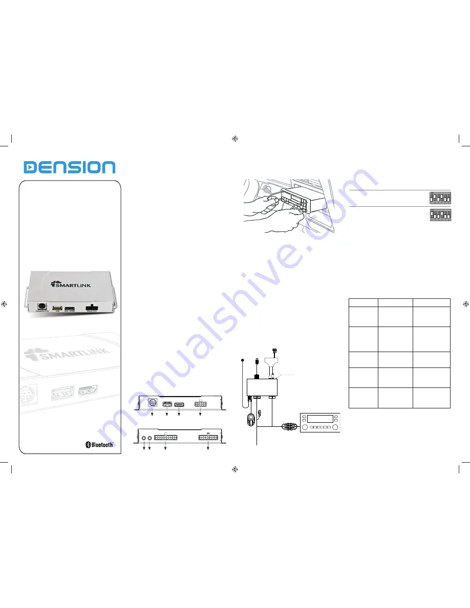
The below diagram (
Fig. 1
) depicts how the different modules connect to
the Smartlink.
(
Fig. 1
)
Smartlink Universal installation diagram
Warning! Do not trap the cables, or leave them in a position where
they may become trapped after refi tting the head unit.
Symptom
Cause
Solution
Status LED is OFF
on the Connector
Port
Wrong power
connection or
installation problem
Check the installation,
make sure that all
cables are connected
properly
Smartlink is not
recognized
Wrong DIP switch
confi guration or
Bypass mode is
selected on the
Connector Port
Check the DIP switches
or change the mode
from Bypass to Active
according to the
manual
No video / audio
signal from
Connector Port
Device is connected
still over the HDMI
Disconnect the device
connected to the HDMI
input
No video content
is visible over the
brake-in video
cable
HDMI source is still
active
Press the ‘B’ button
on the RCP to change
the source to the video
brake-in
Fuzzy, distorted
picture, incorrect
or inverted colors
Wrong video standard
setting
Check the DIP switch
confi guration (PAL/
NTSC) or setting on the
device
5. Troubleshooting
6. Further Assistance
If you need further assistance in using your Dension product, please
contact your local supplier or visit
www.dension.com/en/support
and click
on ‘
Support
’.
Please check also the download section for the latest fi rmware version and
product documentation, as these may provide additional features or easier
use of the product.
On the bottom of the Smartlink hardware, you will fi nd confi guration
switches. Depending on your radio model and video input type you need
to use different settings.
Set the DIP switches on the hardware
Display confi guration for “
PAL
” standard
4. Test and Refi t
Before you refi t the car stereo, test the Smartlink functions with your car
audio and video, making sure all connections are correct and that you have
full functionality.
Note: If during testing you notice any changes or inconsistencies in
the way the car’s electrical system operates, disconnect the Smartlink
product immediately and consult your dealer.
When you have tested everything, refi t your head unit. Take care
not to
trap any wires
or
the Dension product
.
Please mount the module away
from heat or damp surfaces.
Refi t of the Head Unit is the reversal of the removal process for your
specifi c vehicle, as per your manufacturer’s instructions.
Display confi guration for “
NTSC
” standard
Microphone MHL / HDMI cable
Smartlink
hardware
Smartlink
RCP
Audio / Video
Radio
Power, ground and
mute wires
Connector
Port
Video Brake -in
Audio / Video AUX In
Version 1.0


