60
Checking of 4th-axis Position before Carrying Out CALSET
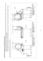
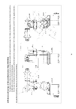
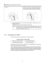
(1) Manually move the 4th-axis section until the hand control signal connector comes
to the upper side.
(2) Dismount the cover from the second arm so that the internal wiring can be
checked.
The cover to dismount for each model is shown below:
VS-6577G VS-6556G
(3) Check that the 4th-axis section is at a designated position.
(The hand control signal connector (CN21) of the second arm comes to the upper
side and the internal wiring is not caught in the crank at this time.)
Checking the 4th-axis position for VS-6577G
The internal wiring is visible in the normal condition.
(It is not visible if caught in the crank.)
Hand control signal
connector (CN21)
Hand control signal
connector (CN21)
Remove 4 screws to
dismount the cover.
Remove 3 screws to
dismount the cover.
4th-axis
motor
Internal wiring
4th-axis motor
Summary of Contents for VS-6556G
Page 1: ...ROBOT Vertical articulated VS G SERIES INSTALLATION MAINTENANCE GUIDE...
Page 6: ......
Page 67: ...49 Reference Drawing of Part A Material A2017 T4...
Page 68: ...50 Reference Drawing of Part B Material A2017 T4 Reference Drawing of Part C Material A2017 T4...
Page 71: ...53 Reference Drawing of Stay for 3rd axis Mechanical End VS6556G Material A2017 T4...
Page 118: ......
Page 120: ......

