8
1.2.3 Securing the Robot Unit
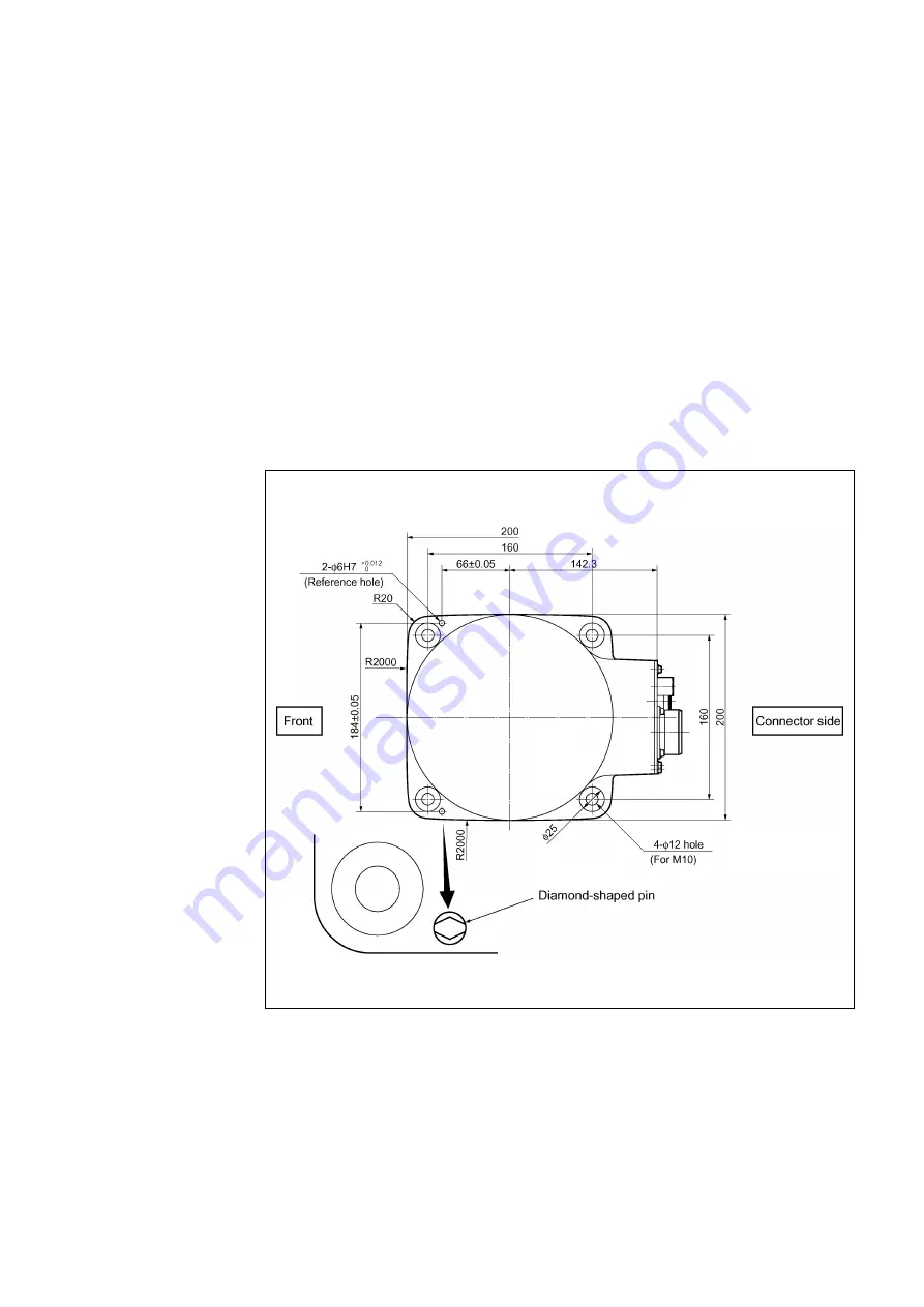
(1) Drill four bolt holes (M10) 20-mm deep or more, and two dowel pin holes (
φ
4, H7 for
diamond shaped pin, and
φ
6H7 for internally threaded positioning pin) 10-mm deep
or more in the robot mounting position where the robot unit is to be secured,
according to the dimension in the figure below.
(2) Drive the diamond-shaped pin into the
φ
4H7 hole so that it orients as shown below.
(3) Drive the internally threaded positioning pin into the
φ
6H7 hole.
NOTE:
Be sure to drive the knock pins. It can minimize positional deviations that may
be caused by the removal/installation of the robot unit for maintenance or the vibration
during operation.
(4) Set the robot unit into place on the robot mount.
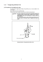
When transporting the robot unit, follow the instructions given in Section 1.2.2
"Transporting the Robot Unit."
(5) Secure the robot unit to the mount with four bolts and plain washers.
⋅
Bolt: M10
×
30 mm (strength class: 12.9)
⋅
Tightening torque: 70
±
14 Nm
Bolt Positions for Securing the Robot Unit (VS-G series)
Summary of Contents for VS-6556G
Page 1: ...ROBOT Vertical articulated VS G SERIES INSTALLATION MAINTENANCE GUIDE...
Page 6: ......
Page 67: ...49 Reference Drawing of Part A Material A2017 T4...
Page 68: ...50 Reference Drawing of Part B Material A2017 T4 Reference Drawing of Part C Material A2017 T4...
Page 71: ...53 Reference Drawing of Stay for 3rd axis Mechanical End VS6556G Material A2017 T4...
Page 118: ......
Page 120: ......


