61
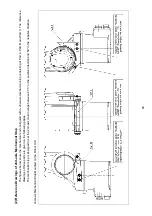
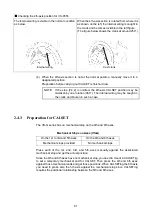
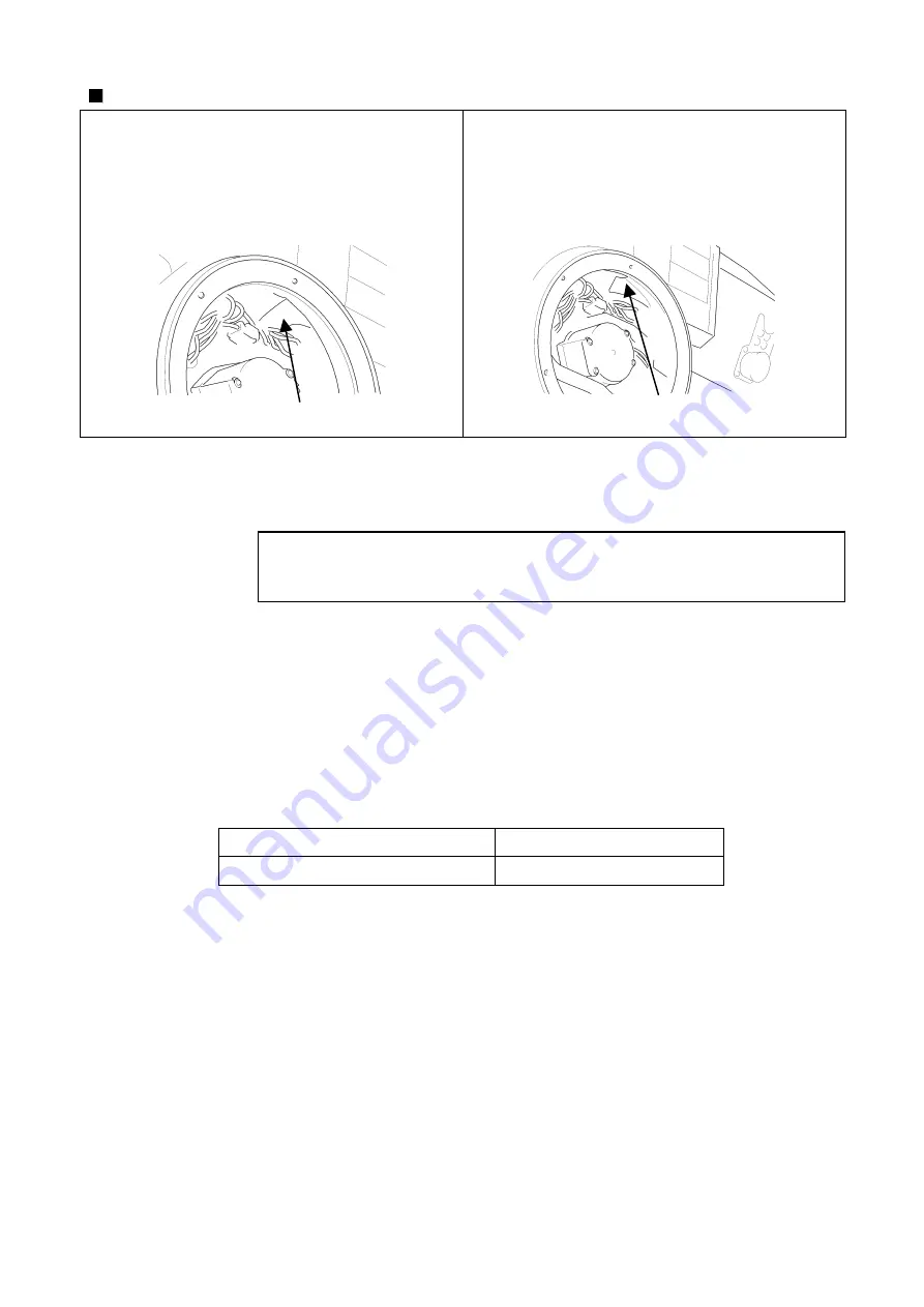
Checking the 4th-axis position for VS-6556
The internal wiring is visible in the normal condition
as below.
When the 4th-axis section is rotated from where it is
as shown on the left, the internal wiring is caught in
the crank and becomes invisible in the left figure.
(The figure below shows the crank at around 250
°
.)
Internal wiring
Cast crank
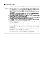
(4) When the 4th-axis section is not at the normal position, manually move it to a
designated position.
Preparation before carrying out CALSET is finished now.
NOTE: If the step [2.4.2] is omitted, the 4th-axis CALSET position may be
mistaken by one rotation (360
°
). The internal wiring may be caught in
the crank and broken in such a case.
2.4.3 Preparation
for
CALSET
The VS-G series has no mechanical stop on the 4th and 6th axes.
Mechanical Stops on Axes (VS-G)
On the 1st to 3rd and 5th axes
On the 4th and 6th axes
Mechanical stops provided
No mechanical stops
Press each of the 1st, 2nd, 3rd, and 5th axes manually against the associated
mechanical stop and get the actual position.
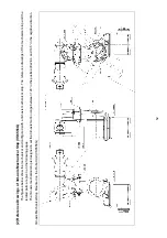
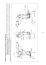
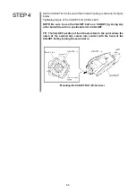
Since the 4th and 6th axes have no mechanical stop, you need to mount a CALSET jig
to set a temporary mechanical end for CALSET. Then press the 4th and 6th axes
against those mechanical ends and get those positions. When CALSETing the 6th axis,
you need to press also the 5th axis against the mechanical stop since CALSETing
requires the positional relationship between the 5th and 6th axes.
Summary of Contents for VS-6556G
Page 1: ...ROBOT Vertical articulated VS G SERIES INSTALLATION MAINTENANCE GUIDE...
Page 6: ......
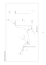
Page 67: ...49 Reference Drawing of Part A Material A2017 T4...
Page 68: ...50 Reference Drawing of Part B Material A2017 T4 Reference Drawing of Part C Material A2017 T4...
Page 71: ...53 Reference Drawing of Stay for 3rd axis Mechanical End VS6556G Material A2017 T4...
Page 118: ......
Page 120: ......


