67
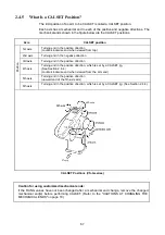
2.4.5 What Is a CALSET Position?
The limit position of an arm to be CALSET is called a CALSET position.
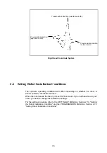
Each axis has a mechanical end in each of the positive and negative directions. The
mechanical ends shown in the figure below are the CALSET positions.
Axis CALSET
position
1st axis
Turning end in the positive direction
(counterclockwise end when viewed from top)
2nd axis
Turning end in the negative direction
3rd axis
Turning end in the positive direction
4th axis
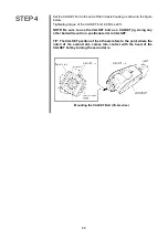
Turning end in the positive direction, which is set by a CALSET jig.
(See Section 2.4.4.)
(counterclockwise end when viewed from the arm end)
5th axis
Turning end in the positive direction
(upward end of the 5th-axis arm)
Pos
iti
on
6th axis
Turning end in the positive direction, which is set by a CALSET jig. (See Section 2.4.4.)
CALSET Positions (VS-G series)
Caution for using customized mechanical ends:
If the RANG values have not been changed after a mechanical end change, remove the changed
mechanical end(s) before performing CALSET. (Refer to the "CAUTIONS AT CHANGING THE
MECHANICAL ENDS" on page 18.)
Summary of Contents for VS-6556G
Page 1: ...ROBOT Vertical articulated VS G SERIES INSTALLATION MAINTENANCE GUIDE...
Page 6: ......
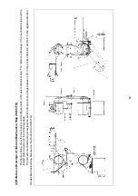
Page 67: ...49 Reference Drawing of Part A Material A2017 T4...
Page 68: ...50 Reference Drawing of Part B Material A2017 T4 Reference Drawing of Part C Material A2017 T4...
Page 71: ...53 Reference Drawing of Stay for 3rd axis Mechanical End VS6556G Material A2017 T4...
Page 118: ......
Page 120: ......


