QUICK START GUIDE , ELITEpro SP™ and ELOG™ 14 SOFTWARE
(cont.)
Creating a Setup table for the ElitePro SP
This step can be completed in the office before your field visit, or it can be completed after the logger has
been installed on the load (field installation is discussed in the next section). In either case, a computer
must be present during logger installation to verify proper configuration and installation (see below).
1.
Start ELOG 15 if it is not already running. With ELOG 15 open, connect the PC to the ElitePro SP
using a USB cable. The ElitePro SP automatically connects to the PC. If it does not, choose the correct
COM port from the Tools > PC Setup > Port drop down menu.
2.
Synchronize the logger clock to the computer by clicking Logger > Logger Clock > Synchronize Time
To Match PC.
3.
The Setup Table tells the ElitePro SP logger what to measure, how often, etc.
a) Click on the ELOG 15 File menu and select New > Setup Table File > OK.
b) If prompted to Select a Setup Table Type, select ElitePro SP and click OK to continue.
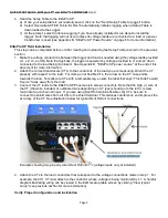
c) Before completing other values, start by finding the Quick Setups area and clicking on one of the
four rapid setup (“Speed”) buttons corresponding to your load configuration (see illustration below).
These buttons reset most fields to default values.
d)
Choose the CT type in the resulting dialog box. If you are using 333mV CTs, enter the value that
corresponds with the nominal rating of the CTs in Amps which is printed on the CT. See below if
you are using more than one CT value. If you are using Dent’s RoCoil (blue flexible coil) CTs, be
sure to make that selection here (no Amperage value is entered for RoCoil CTs). Click OK.
e) (Optional) Change the label in the Setup Table Name if desired.
f) Set the Data Interval to the desired logging interval.
g) Make desired Data Logging Start and Stop selections. If you are launching multiple loggers,
consider choosing a specific start time for all of them (instead of choosing to Start Immediately for
each one). This allows easier alignment of data across loggers during analysis.
h) (
Optional
) Update the label in Power Channel Names if desired.
i) If needed, update the current transducer (CT) value for any CTs that are different from the default
value provided earlier.
j) Input the phase shift (if known and if different from the default value of 1.1°) for the selected CT.
k) Select desired parameters you wish to log. For example, to log average voltage values, click the
down arrow to the right of the Volts field and click "Average". Repeat for all other desired values as
needed. Typical values include V(avg), A(avg), kW(avg), kWh, and PF(avg). Note: be sure to check
the "Memory Capacity" value in the upper right of the screen to confirm there is enough memory for
your desired data and logging interval.
l)
(
Optional
) Click on File > Save As… to save the Setup Table to the computer’s hard drive. Name
the table as desired and click Save.
Maximum Logging
duration
Click for wiring
diagrams
“Speed” buttons
Logging start
and stop times
Send setup
table to logger
Page 4


