background image


41 


DENT Instruments 

PowerScout HD 

Meter Installation 


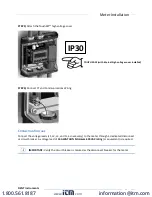
STEP 5)

 Attach 

the TouchSāf™ 

high voltage cover


STEP 6)

 Connect CT and Communications Wiring  


C

ONNECTING 

V

OLTAGE


Connect the voltage leads (L1, L2, L3, and N, as necessary) to the meter through a dedicated disconnect 

or circuit breaker. A voltage lead of 

14 AWG THHN Minimum 600VAC rating

 (or equivalent) is required.  


IMPORTANT: 

Verify the circuit breaker is marked as the disconnect breaker for the meter.  


IP30 


TOUCH SAFE (with internal high voltage cover installed) 
 

www.

.com

information@itm.com

1.800.561.8187

Summary of Contents for PowerScout 12 HD

Page 1: ...June 30 2020 OPERATOR S GUIDE PowerScout HD Networked Power Meters PowerScout 3 HD PowerScout 12 HD PowerScout 24 HD PowerScout 48 HD and ViewPoint HD Software www com information itm com 1 800 561 8187 ...

Page 2: ... reproduced or distributed without written permission from DENT Instruments PowerScout ViewPoint TouchSāf and PhaseChek are trademarks of DENT Instruments Inc Windows Windows 7 Windows 8 and Windows 10 are registered trademarks of Microsoft Corporation Mac and macOS are registered trademarks of Apple Inc www com information itm com 1 800 561 8187 ...

Page 3: ...gramming and Scripting Overview 17 Meter Configuration Details 18 Install the ViewPoint HD Software 18 TYPICAL INSTALLATION 18 CUSTOM INSTALLATION 19 INSTALLATION TROUBLESHOOTING 19 UNINSTALLATION PROCEDURE 20 Connection Configuration Options Using ViewPoint HD 20 USB Connection Power Communications 21 Ethernet Network Connections 22 DYNAMIC HOST CONFIGURATION PROTOCOL DHCP 22 DIRECT 22 LCD User I...

Page 4: ...D Meter in a 4 wire 3 ɸ Service Panel 45 Wiring the PSHD Meter in a Single Phase Application 46 Current Transformer Basics 47 Wiring the CTs to Multi Circuit PSHD Meters 48 Wiring CTs to PS3HD Meters 49 Communication Verification Details 51 Physical Connections on an RS 485 Multidrop Network 51 Communication Verification 52 ViewPoint HD PSHD Web App 53 Physical Interface Verification 53 Serial Set...

Page 5: ... vs System Scope 65 Physical Implementation on PS48HD Meters 66 Configuring Element and Channel Register for Service Types 67 Configuring System Registers 69 Modbus Protocol Commands 69 Floating Point Registry Entry 73 BACnet 77 BACnet Segmentation 77 BACnet Structured View 77 Appendix A PSHD LCD USER INTERFACE Menu Navigation 79 About Meter Multi Circuit PSHD Meters 79 Menu Navigation Multi Circu...

Page 6: ...ior Version of ViewPoint HD Has Been Installed 88 SOFTWARE UPDATE For Users with ViewPoint HD Software Already Installed 89 CUSTOM INSTALLATION For Users Who Cannot Use the BATCH File 90 TROUBLESHOOTING 92 Appendix F PSHD Technical Specifications 93 www com information itm com 1 800 561 8187 ...

Page 7: ... communication interfaces include Ethernet LAN or RS 485 serial BACnet MS TP and Modbus RTU are the two communication protocols that operate over an RS 485 serial network and BACnet IP and Modbus TCP are supported over Ethernet A USB port is also provided as the preferred connection for on site configuration and can be run concurrently with an RTU Unpacking the Unit The PSHD can be ordered with op...

Page 8: ...cate of Calibration COC USB Cable cable type dependent on meter choice o USB A to B Cable PS12 PS24 PS48 one per order o USB A to C Cable PS3HD one per order PowerScout HD Anatomy All user connections are made on the circuit board Connectors are identified by function and include polarity markers www com information itm com 1 800 561 8187 ...

Page 9: ...9 DENT Instruments PowerScout HD Introduction PS24HD PS48HD mounting plate version shown POWERSCOUT 12 HD PS12HD Enclosure with cover removed www com information itm com 1 800 561 8187 ...

Page 10: ...ENT Instruments PowerScout HD Introduction POWERSCOUT 3HD AVAILABLE CONFIGURATIONS PS3HD Wall Mount Option Enclosure with Cover Removed PS3HD DIN Rail Mount Option www com information itm com 1 800 561 8187 ...

Page 11: ... Use approved protection when operating the device CAUTION THIS METER MAY CONTAIN LIFE THREATENING VOLTAGES QUALIFIED PERSONNEL MUST DISCONNECT ALL HIGH VOLTAGE WIRING BEFORE SERVICING THE METER WITH THE HIGH VOLTAGE TOUCH SAFE TouchSāf COVER REMOVED Symbols on Equipment Denotes caution See manual for a description of the meanings DENOTES HIGH VOLTAGE RISK OF ELECTRICAL SHOCK LIFE THREATENING VOLT...

Page 12: ...ment Secure current transformer and route conductors so that they do not directly contact live terminals or bus CTs shall be listed to UL2808 where applicable Meter Installation Safety Requirements PSHDmeters must be installed in accordance with local electrical codes Use copper conductors only Connection to the mains terminals shall be made with 14 AWG minimum wire gauge External secondary inputs...

Page 13: ...rview of typical process activities followed by details in the next section CONFIGURATION DATA VIEWING OPTIONS The PowerScout HD meter has three methods for configuration and data viewing The most powerful interface is ViewPoint HD a Microsoft Windows application that runs on PCs or Tablets ViewPoint HD is encouraged for complex installations and is required for configuring advanced functions like...

Page 14: ...All Meter Parameters Waveform Capture Harmonic Analysis All Element View Phasor Plot Alarms All Meter Parameters Single Element View Voltage Current VA VAR kWh Single Element View All Meter Parameters Configuration Entire Meter Visual Guides Copy Paste Entire Meter Sans Alarms Text Based Communications Only Entire Meter Register Based Security PINs Enforced Factory Support Level 3 Read Only Level ...

Page 15: ...Point HD Software Connect USB Ethernet cable from PC to meter Establish communication with meter Firmware update if desired Configure software for anticipated meter setup Field wiring documentation Set alarms Set security PINs Meter Installation Overview Performed by licensed electrician Tools Typical Work Mounting hardware user supplied Wiring supplies labels wire ties Tablet Smart Device or Lapt...

Page 16: ...wire terminations if required Confirm meter communication settings Meter health metrics check for setup errors Analytics ViewPoint HD Correct instrumentation Set alarms Set security PINs Checklist RTU Programming and Scripting Overview Tools Typical Work Laptop PC Remote Access to RTU Remote troubleshooting Register List Confirm meter communication settings Confirm communication protocols Exercise...

Page 17: ...interface The web browser can be accessed from the USB port to support macOS users Install the ViewPoint HD Software The following directions assume that this is a fresh installation of ViewPoint HD software If you are upgrading ViewPoint HD from a previous version follow the Uninstallation Procedure at the end of this section prior to installing new software Instructions can also be found in the ...

Page 18: ... second step is handled automatically in the batch file INSTALLATION TROUBLESHOOTING Successful installation of ViewPoint HD may be prevented by settings specific to your PC for the following reasons 1 Anti virus protection software may interfere with the installation of ViewPoint HD If the installation does not complete for this reason try temporarily disabling the virus protection software on yo...

Page 19: ... application and press the Uninstall button After uninstallation is complete perform the final steps to completely remove program s support files from your hard drive 1 Open Windows File Explorer and navigate to the Local Disk typically C 2 Delete the folder titled ViewPoint HD Once the program has been uninstalled and the support files have been removed follow the Typical Installation instruction...

Page 20: ...r when connected via USB A to B Cable For use with PS12HD PS24HD PS48HD A to C Cable For use with PS3HD Preferred Connection via USB Cable 2 Launch the ViewPoint HD application and press the CONNECT OVER USB button on the pop up window The meter should now be communicating The ViewPoint HD application offers visual guides and context help to facilitate meter configuration Please read the ViewPoint...

Page 21: ...de to prevent IP conflicts with other equipment The meter is expecting to receive an IP address from a DHCP service provided by a router Layer 3 switch or a server providing DHCP service Under this configuration as long as the PSHD meter and the host PC are requesting an IP address from the same DHCP service provider they will be able to communicate Upon powering up the PSHD meter will indicate th...

Page 22: ...tion read the ViewPoint HD overview section below and or watch the tutorial videos on the DENT website for additional information on configuring the meter Meters without an LCD User Interface A PSHD meter without an LCD user interface has no way to communicate to the user its IP address and is only recommended if the meter has been previously set to a known static address Setting the IP address mu...

Page 23: ...sired meter and select OK Test or Setup Note that the effectiveness of this technique is highly dependent on the configuration of the PC running ViewPoint HD which may have more than one network card and the network configuration Rescans can be used to make multiple attempts to locate a particular meter on busy networks UDP has no built in retry provisions LAUNCH CONFIGURATOR The final option in t...

Page 24: ...ontent filter for viewing basic metering data or extended data that can be helpful in troubleshooting The information displayed in the drop down list for each filter setting is summarized below Display Data Monitor Power Energy Demand Monitor Power Energy Demand Power Factor Waveform Capture Harmonics Phasor Plot Setup Meter Setup Communication Setup Advanced About the Meter Setup Meter Setup Comm...

Page 25: ...els are selected in the drop down list and are identified by a combination of CT image and amperage range The parameters for the selected CT are automatically populated This information can be edited for custom use Service Type Select a service type from the drop down list A selection populates the fields with pre configured service type information User selectable fields are shown in white Greyed...

Page 26: ... Discover how to use the power meter as an oscilloscope to view electrical waveforms and identify harmonic distortion Phasor Plot PSHD Phasor Plot Phasor Plot Demo mp4 Discover how to use the electrical phasor plot to graphically confirm correct CT placement and orientation Alarms Demo PSHD Alarms Demo Alarms demo mp4 Discover how to configure and manage event alarms for conditions such as over cu...

Page 27: ...28 DENT Instruments PowerScout HD Meter Configuration CONFIGURING ELECTRICAL COMPONENTS USING VIEWPOINT HD www com information itm com 1 800 561 8187 ...

Page 28: ...Cnet Modbus OR BACnet Modbus BACnet Modbus BACnet Set Serial Settings Set Modbus Address Set Serial Settings Set Device ID Set Max Masters optional Set Max Info Frames optional DHCP OR STATIC Set Device ID DHCP Static IP Set Static IP Address Set Subnet Mask Set Gateway Mask Press SEND SETUP TO METER Set MS TP Address Set BACnet Port BBMD optional Set Default Gateway www com information itm com 1 ...

Page 29: ...tage Input 2 PS24HD and PS48HD meters for L N and L L voltage measurements Alarms are activated by toggling the Enable button for each voltage reference independently and pressing the Send to Meter button An example of a 10 drop in a 480 VAC Delta System is shown below Only Line to Line measurements are enabled Lower Alarm Voltage values can be copied to other voltage references using the Copy but...

Page 30: ...are notified of an alarm via a hardware circuit normally low that can be wired to an interrupt input Details about which alarm triggered are determined by reading the status registers under the alarm block 2450 2500 Alarms no longer need to be cleared by the host The alarm will be expressed whenever the condition exists and will clear itself if measured values exceed the trigger points Alarm condi...

Page 31: ...ar window and allows the user to set any desired date and time Set Time to Now populates the sets the time and date to match the PC Press the OK button to commit this time to the RTC chip onboard the meter Real Time Clock Power Source The RTC integrated circuit is a standalone low power circuit within the PSHD meter Time is kept in the absence of a connected external power source AC or USB power b...

Page 32: ...enu Click the Download button By default the name of the data file will include the Serial Number of the Meter and the System Description followed by Datalog see below After pressing OK the entire data path will be displayed The data log is a Comma Separated Values CSV file that can be opened in Excel or another program The data will be listed in chronological order according to an internal 32 bit...

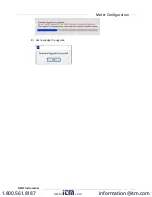
Page 33: ...ollows 1 Download the Latest Media Distribution from the DENT website and review the change log 2 Un install and Re install ViewPoint HD software ViewPoint HD uninstallation directions can be found in the Meter Configuration section of this guide 3 Locate the appropriate binary file within the Firmware folder of the Media Release example below 4 Connect to the meter using ViewPointHD and locating ...

Page 34: ...35 DENT Instruments PowerScout HD Meter Configuration 8 Acknowledge the upgrade www com information itm com 1 800 561 8187 ...

Page 35: ... subnet as the PSHD meter 3 Open a web browser 4 Enter the PSHD s Ethernet address into the web browser CONNECT TO WEB APP USING USB In cases where the Ethernet port is already connected to a building network and the ViewPoint HD application has not been installed on the PC the meter can still be configured using the meter s built in web server 1 Connect your device to the meter via USB cable 2 Op...

Page 36: ...ersion of 10 11 1 or higher 2 Drag the file dentinstruments 2 03a1 dmg onto the desktop 3 Double click the dmg file to initiate the Mac installer 4 Follow the installation prompts 5 Reboot the Mac after the installation process is complete 6 Connect the PSHD meter to the Mac with USB cable 7 Open Safari browser and type IP address 169 254 1 5 to access the PSHD Web App 8 If no login credentials ar...

Page 37: ...and to the PSHD meter Meter Mounting Configurations DENT PowerScout HD meters are sold in several form factors Wall mounted enclosures are designed to be connected to electrical conduit Plate or rail versions are ready to be mounted inside a user supplied UL NEMA certified enclosure Care should be taken to not flex the circuit board during mounting Mounting Options PS48 HD PS24 HD PS12 HD PS3HD En...

Page 38: ...ver screws 2x provided STEP 2 Locate mark and drill wall mounting points 2x 6x user supplied The plastic enclosure itself can be used as a template for marking the drill locations on the wall If the meter is not available for use as a drill template a drawing indicating the spacing between mounting holes can be found in the appendix The centerline holes are intended for fastening to wall studs If ...

Page 39: ...ents PowerScout HD Meter Installation STEP 3 Mount conduit fittings conduits and blanking plugs STEP 4 Connect voltage leads DO NOT ENERGIZE METER WITH VOLTAGE COVER REMOVED www com information itm com 1 800 561 8187 ...

Page 40: ...e voltage leads L1 L2 L3 and N as necessary to the meter through a dedicated disconnect or circuit breaker A voltage lead of 14 AWG THHN Minimum 600VAC rating or equivalent is required IMPORTANT Verify the circuit breaker is marked as the disconnect breaker for the meter IP30 TOUCH SAFE with internal high voltage cover installed www com information itm com 1 800 561 8187 ...

Page 41: ...ce for voltage CT and communication wires to be routed within the enclosure The UL approved enclosure is customer supplied STEP 2 Mount the meter on the DIN rail by pressing the top edge of the DIN rail channel on the meter into the top of the DIN rail itself and then pushing the meter firmly towards the DIN rail so that it clicks into place The meter can be released from the DIN rail by using a s...

Page 42: ...g CONNECTING VOLTAGE Connect the voltage leads L1 L2 L3 and N as necessary to the meter through a dedicated disconnect or circuit breaker A voltage lead of 14 AWG THHN Minimum 600VAC rating or equivalent is required IMPORTANT Verify the circuit breaker is marked as the disconnect breaker for the meter www com information itm com 1 800 561 8187 ...

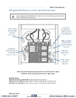
Page 43: ...1 N or L2 N 110 VAC Lighting Appliance Living Zone Single Phase L1 L2 220 VAC Water Heater or other equipment with no Neutral wire Split Phase L1 L2 220 VAC Service Entrance Dryers or equipment with Neutral wire 3 Wire 1 Phase Used on MAINS L1 N L2 N RōCoil CTs Shown Single Phase 110 VAC Plug Loads L1 N or L2 N Split Core CTs Shown Single Phase 220 VAC Load L1 L2 Meter is powered from L1 to L2 on ...

Page 44: ... the neutral terminal is left open L L measurements will be accurate but L N measurements may not be symmetric If a ground wire is connected to the Neutral terminal 500 uA will flow into the ground wire Connect the Neutral wire to the VIN1 Neutral Terminal on the PSHD Meter Meter Power Connect all phases to the VIN1 terminal Label as PowerScout Disconnect 3 Wire 3 ɸ DELTA load No possibility of Ne...

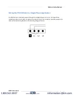
Page 45: ...n The PSHD meter is internally powered through the voltage between L1 and L2 For Single Phase installations where no L2 exists it is advised to jumper N to L2 This connection provides power to the meter while maintaining Neutral as the metering voltage reference www com information itm com 1 800 561 8187 ...

Page 46: ...toward load or as instructed by CT label Arrow points away from Panel or as instructed by CT label Placed on First Conductor of voltage Reference L1 L2 circuits are placed on L1 Observe wiring color and polarity On RōCoils use the Shield wire connect to PCB terminal marked S Wiring Guide for CT Types Split Hinged Solid Core CTs RōCoil CTs White Positive Black Negative no shield White Positive Brow...

Page 47: ...to connect CTs to the PSHD meter for each service type For service types that are not specifically listed it is recommended to choose single phase service and configure each channel individually Three phase loads are illustrated on the left and split phase loads on the right as an example only Elements are fully interchangeable on the meter www com information itm com 1 800 561 8187 ...

Page 48: ...s below represent CT and voltage connections between the PowerScout 3 HD and the most common service types For specific wiring questions outside the scope of this document contact DENT technical support Two Wire Single Phase Three Wire Single Phase www com information itm com 1 800 561 8187 ...

Page 49: ...50 DENT Instruments PowerScout HD Meter Installation Two CT Three Wire Delta Four Wire Wye www com information itm com 1 800 561 8187 ...

Page 50: ...guration DOES NOT have a TouchSāf High Voltage Cover and should not be touched while powered from line voltage Communications settings and real time data values can be confirmed quickly using the LCD interface if equipped When significant setup modifications are anticipated a computer interface is recommended Physical Connections on an RS 485 Multidrop Network The PSHD meter uses a 2 Wire Half Dup...

Page 51: ... to the next A Reverse Contrast entry in the documentation indicates the active menu item in a list which corresponds to a blinking character in the physical LCD The ENTER button is used to select a property and up down buttons are used to select among the values supported by the meter Note that changes to the meter configuration are limited to the communication interface using the LCD If addition...

Page 52: ...videos for ViewPoint HD or the PSHD Web App Physical Interface Verification SERIAL SETUP VERIFICATION In a multidrop serial network the host data format settings are typically known or specified and the slave is adjusted to match In some cases long wiring runs etc it may be necessary to experiment in determining the fastest allowable baud rate for a given wiring configuration by changing BOTH the ...

Page 53: ...n IT department to avoid multiple devices on the same network This scheme is usually used when an RTU is expecting to find the meter at a specific IP address Protocol Verification The network protocol is typically specified as part of the installation BACnet MS TP and Modbus RTU are the two communication protocols that operate over an RS 485 serial network and BACnet IP and Modbus TCP are the prot...

Page 54: ... BACnet IP Broadcast Management Device is set to 0 0 0 0 at default and can be changed through a software tool to allow discovery across networks Pulse Outputs Discontinued Early PS48HD meters Hardware revision H running firmware version 1 012 were equipped with 2 pulse outputs User feedback indicated that inputs would be more useful than outputs In response to this the pulse direction was reverse...

Page 55: ...ustomer supplied pullup resistor A 10k ohm watt resistor is the recommended load for this circuit For more information regarding setting up alarms see the section Configuring Alarms earlier in this manual Refer to the register list ViewPoint HD or instructional videos for more information Note The Master Alarm relay is intended for low voltage DC connections 12 Volt Auxiliary Power The PS12HD PS24...

Page 56: ...T Instruments PowerScout HD devices If full rated current is drawn from this terminal the minimum operating voltage of the L1 L2 power supply is 100 VAC This option is unavailable on the PS3HD www com information itm com 1 800 561 8187 ...

Page 57: ...ure below The default user entry on power up or time out is 0000 which satisfies both the Read Only and the Read Write default register settings USING THE PERMISSION REGISTERS The PSHD meter uses both a Read Only register and a Read Write register to compare against user entrees from the meter s keypad or PSHD Web App form entry Both internal permission registers have a default value of 0000 A con...

Page 58: ...PIN 0000 allows a new user to reset the Read Write PIN from either the PSHD Web App or ViewPoint HD Permissions cannot be set through the LCD interface READING PINS OVER MODBUS ViewPoint HD can be used to directly report the Read Only and Read Write PINs under the Advanced Tab passwords The value reported by ViewPoint HD is the value as entered in the web page or LCD interface PINs are also access...

Page 59: ...s for a PS3HD meter The LCD user interface will list the elements having at least one channel with a low power factor CHECK ELEMENTS A EF Use the navigation buttons to highlight a specific element and hit enter or just hit enter and move from element to element using the keys Within each element identified on the top line of the display the status of each channel is identified as OK PF 0 55 or bad...

Page 60: ...solute displacement power factor of a load is below 0 55 an angle greater than 57 degrees between voltage and current the PSHD meter will flag it as a phasing error ViewPoint HD has a Phasor Plot feature that can be used to study the voltage and current vectors of a given meter element Check for Low Power Factor ViewPoint HD Real Time Values All power factors 0 55 are shown in RED PSHD Web App Rea...

Page 61: ...e amplitude of the Power Factor A moderate power factor 0 7 in concert with a negative power is a clue that the CT is on backwards but is on the correct phase Electrical Power Quadrants with Reversed CT shown Check that the wattage has the correct sign Designated for loads ViewPoint HD Real Time Values Confirm Sign of Power For All Elements PSHD Web App Real Time Values Confirm Sign of Power For A...

Page 62: ...erall harmonic content in power THD based on its measurement of Power Var and Apparent Power as illustrated in the figure below This method cannot indicate the harmonic number or distribution but provides the overall harmonic content In many circumstances users are interested in the harmonic content of current In cases where the voltage is very sinusoidal the THD measurement is a good estimate of ...

Page 63: ...ding ratios or other scaling adjustments to be included in the meter processing to eliminate post process scaling Adjustments for voltage are global to the meter while CT s can be adjusted on a channel by channel basis The multiplier is a floating point number and can also be used for post installation calibration if desired Default value is 1 0 Values below 0 9 are disallowed CT PHASE SHIFTS Curr...

Page 64: ...8HD PCBA i e A B C D In a three phase power system these correspond to electric circuits Logically the term Element describes the scope of a data item register or point Modbus register or BACnet object Each Element based point is accessed by choosing the appropriate Modbus address BACnet object range or BACnet structured view Elements in turn have points that refer to individual channels or to SUM...

Page 65: ... example The CT nomenclature will be used to allow users to group CT channels into Virtual Elements that are not constrained to a three phase structure and have additional flexibility To suit both Classic and Virtual Element VE meters with the same base design the printed circuit board has been revised to indicate both nomenclatures using a two color silk screen something like a scientific calcula...

Page 66: ... 2224 2225 2221 2222 2226 CH2 2229 2232 2227 2228 2233 2234 2230 2231 2235 CH3 2238 2241 2236 2237 2242 2243 2239 2240 2244 Configurations 4 Wire 3 ɸ Wye Service Type 1 V_Input 1 or 2 Description 31 Char Channels Volt Ref CT Type Range Phase Shift CT Multiplier CT Sign CH1 L1 N 1 mV 1 or RōCoil 2 Any 0A 4 0 to 4 0 Any 0 1 0 or 1 CH2 L2 N 2 mV 1 or RōCoil 2 Any 0A 4 0 to 4 0 Any 0 1 0 or 1 CH3 L3 N...

Page 67: ...V 1 or RōCoil 2 Any 0A 4 0 to 4 0 Any 0 1 0 or 1 CH3 L3 N 3 OFF 0 Any 0A 4 0 to 4 0 Any 0 1 0 or 1 Even though CH3 is not used for computation it is recommended that the CT settings reflect those from CH1 rather than being left at factory default to facilitate configuration validation from the RTU Disabled OFF Service Type 5 V_Input 1 or 2 Description 31 Char Channels Volt Ref CT Type Range Phase ...

Page 68: ...tiple registers useful but not required for 32 bit values and strings Report Slave ID 17 0x11 Used to read information from the identified PSHD meter SLAVE ADDRESS For Modbus TCP the base slave address or unit address as the Modbus TCP specification calls it is fixed at 1 Refer to the section Serial Protocols for additional information on setting the Slave Address and finding the address of a spec...

Page 69: ...ER ID FC ADDR DATA CRC 01 06 04 37 31 39 EC B6 01 06 04 38 32 2E 9C 4B 01 06 04 39 31 36 CD 71 01 06 04 3A 38 2E 3B 2B 01 06 04 3B 32 2E 6C 4B 01 06 04 3C 39 00 5A A6 01 06 04 3D 00 00 19 36 01 06 04 3E 00 00 E9 36 VIA MODBUS RTU SERIAL USING FUNCTION CODE 16 WRITE MULTIPLE REGISTER ID FC ADDR REGS LN DATA0 DATA1 DATA2 DATA3 DATA4 DATA5 DATA6 DATA7 CRC 01 10 04 37 00 08 10 31 39 32 2E 31 36 38 2E ...

Page 70: ... 69 6E 73 20 62 6C 64 20 31 30 31 20 00 00 00 00 00 00 00 00 00 00 00 00 00 00 00 00 00 00 START STOP Specific Implementation Examples Element A set to ID 1 VIA MODBUS RTU SERIAL USING FUNCTION CODE 6 WRITE SINGLE REGISTER ID FC ADDR DATA CRC 01 06 0A 39 4D 61 AE A7 01 06 0A 3A 69 6E 05 A3 01 06 0A 3B 73 20 DF 37 01 06 0A 3C 62 6C 63 53 01 06 0A 3D 64 20 30 C6 01 06 0A 3E 31 30 FE 5A 01 06 0A 3F 3...

Page 71: ...00 01 8F 00 00 00 06 01 06 0A 41 00 00 01 90 00 00 00 06 01 06 0A 42 00 00 01 91 00 00 00 06 01 06 0A 43 00 00 01 92 00 00 00 06 01 06 0A 44 00 00 01 93 00 00 00 06 01 06 0A 45 00 00 01 94 00 00 00 06 01 06 0A 46 00 00 01 95 00 00 00 06 01 06 0A 47 00 00 01 96 00 00 00 06 01 06 0A 48 00 00 VIA MODBUS TCP ETHERNET USING FUNCTION CODE 16 WRITE MULTIPLE REGISTER TXNID PROID LENGT ID FC ADDR REGS LN D...

Page 72: ... meter data is stored as MSW LSW which may take some trial and error to identify in the RTU setup Float ABCD is an example of the how this RTU identifies the matching byte order It is anticipated that command line programmers or script writers may prefer to enter data in hexadecimal format Non programmers using Modbus or BACnet utilities or those using ViewPoint HD may prefer to use decimal notati...

Page 73: ...uired these decimal values can be converted using a utility such as the MS Windows Calculator under Programmer mode as shown below After padding we also arrive at 0x42C8 0x0000 as the MSW and LSW register values respectively Step 2 Identify which configuration registers control the CH1 CT Full Scale Rating a Refer to the MS Excel Register List USB drive or at b Use ViewPoint HD to discover the add...

Page 74: ... registers controlled or displayed by this window The desired control registers are 2218 MSW and 2219 LSW Convert the register addresses of interest into hexadecimal notation if required STEP 3 Calculate the CRC 16 Modbus RTU for the expression There are several variations of the CRC016 ensure the one you are using is for Modbus The CRC is entered LSB first Enter the Entire Expression into a CRC C...

Page 75: ...A0 DATA1 01 87 00 00 00 0B 01 10 08 AA 00 02 04 42 C8 00 00 COMMANDS REQUIRING A PROCESSOR RESET Register manipulation of communication protocols or addressing require that the PSHD performs a soft reset in order to take effect Register 2100 can receive a user command to facilitate this process BACnet users write a 1 and Modbus users write 1234 to affect a soft reset The PSHD reboot time is approx...

Page 76: ...can be set from ViewPoint HD or through character string object 2264 A value of 0 0 0 0 disables foreign device registration This process requires a processor soft reset BACNET SEGMENTATION The PSHD meter does not support BACnet Segmentation Segmentation is required when the requested data is longer than the underlying data packet size limitations of the protocol i e the Maximum Transmission Unit ...

Page 77: ...xplorer tools have additional sorting capabilities PSHD Supported BACnet Object Types Object Type Abbr Typical Usage Analog Input AI Meter Readings floating point numeric inputs Analog Value AV Analog User Settings floating point numeric outputs Binary Value BV User Boolean Settings Multi State Value MSV Enumerated Settings BitString Value BSV Bitfield Status Words and Settings Positive Integer Va...

Page 78: ...ges The About Meter menu is the most commonly accessed item which requires 5 down presses or 1 up rolling menu to access The About Meter menu contains the following items which are displayed 4 lines at a time and accessed by using the keys on the front display PS12HD PS24HD and PS48HD Information for the PS3HD is similar and is accessed by using the navigation wheel www com information itm com 1 8...

Page 79: ...80 DENT Instruments PowerScout HD Appendix A MENU NAVIGATION MULTI CIRCUIT PSHD METERS www com information itm com 1 800 561 8187 ...

Page 80: ...81 DENT Instruments PowerScout HD Appendix A COMMUNICATION NAVIGATION MULTI CIRCUIT PSHD METERS www com information itm com 1 800 561 8187 ...

Page 81: ...50 23 2 4000 3 800 2 W 1 50 23 2 4000 3 800 2 kWH 1 453 2 2 445 3 3 543 2 VA 1 50 23 2 4000 3 800 2 VAR 1 50 23 2 4000 3 800 2 SYS aPF 1 0 Pk Demand 12874 CT1 Type RoCoil Rating 5000 CT2 Type RoCoil Rating 5000 CT3 Type RoCoil Rating 5000 SN P031501001 FW v2 10 RS485 115200 Addr 1 Protocol BACnet 192 168 100 101 www com information itm com 1 800 561 8187 ...

Page 82: ...83 DENT Instruments PowerScout HD Appendix B APPENDIX B ENCLOSURE DIMENSIONS PS24HD PS48HD Enclosure Dimensions PS12HD Enclosure Dimensions www com information itm com 1 800 561 8187 ...

Page 83: ...84 Appendix B DENT Instruments PowerScout HD PS3HD Wall Mount Enclosure Dimensions PS3HD DIN Rail Enclosure Dimensions www com information itm com 1 800 561 8187 ...

Page 84: ...werScout HD Appendix D APPENDIX C MOUNTING TEMPLATES Enclosure Internal Mounting Hole Locations Not to Scale PS24HD PS48HD Drill Template PS12HD Drill Template PS3HD Drill Template www com information itm com 1 800 561 8187 ...

Page 85: ...rScout HD Appendix C Sheet Metal Plate Mounting Hole Locations PS12HD PS24HD PS48HD only Not to Scale PS24HD PS48HD Mounting Plate Drill Template PS12HD Mounting Plate Drill Template www com information itm com 1 800 561 8187 ...

Page 86: ...Number Type Amps Phase Shift CT RGT12 0005 Millivolt 5 0 05 CT RGT12 0020 Millivolt 20 0 CT RGT12 0050 Millivolt 50 0 01 CT RGT12 0100 Millivolt 100 0 CT HSC 020 Millivolt 20 1 11 CT HSC 050 Millivolt 50 1 02 CT HMC 100 Millivolt 100 0 26 CT HMC 200 Millivolt 200 0 22 CT SRS 005 Millivolt 5 0 1 CT SRS 050 Millivolt 50 0 02 CT SRL 100 Millivolt 100 0 09 CT SRL 200 Millivolt 200 0 1 CT SRL 400 Milli...

Page 87: ...py the MEDIA DISTRIBUTION folder to your local hard drive Installations attempted from Thumb Drives or across a Network may not be successful 2 Locate and double click on the Run Me to Install ViewPoint HD bat batch file highlighted below The batch file installs both the application and drivers needed for ViewPoint HD The batch file will create a folder called ViewPoint HD on the root of the C dri...

Page 88: ...sion of ViewPoint HD Before running the installer take the following steps 1 Locate the ViewPoint HD application within Windows Program and Features a Right click on the program in the Windows Start Menu and select Uninstall 2 Delete the ViewPoint HD folder from the C drive 3 Proceed with the steps listed under NEW INSTALLATIONS a Your installation will skip the installation of drivers and instead...

Page 89: ... Windows Tools The user will need to install the required drivers as a separate process Within the ViewPoint HD Installer Directory there is a folder alongside the batch file The contents of this folder contain supporting documents Install the LabVIEW Run Time Engine first using setup exe in the LVRTE folder shown below Then install the Viewer application software by running the setup exe from the...

Page 90: ...zard and allows users to change the installation directory Follow the prompts to complete the installation Create a folder named ViewPoint HD in the C directory and copy the folder named Local shown below to the newly created C ViewPoint HD folder www com information itm com 1 800 561 8187 ...

Page 91: ...ectories 1 Checking for User Account Permissions a Access the Control Panel on your computer b Click on User Accounts c Confirm Permission i User types are Administrator Standard and Guest 2 Install as Administrator If your user profile is not listed as an Administrator some installations allow a temporary permission as follows a Right click on the Run Me to Install ViewPoint HD bat and select Run...

Page 92: ...t capacity Power Out PS12HD PS24HD PS48HD only Unregulated 12VDC output 200 mA self resetting fuse Waveform Sampling 1 8 kHz Parameter Update Rate 1 second Interval Data Recording Energy kWh values are recorded every 15 minutes for 63 days downloadable log Each record is time stamped Measurements Volts Amps kW kVAR kVA aPF dPF kW demand kVA demand Import Received kWh Export Delivered kWh Net kWh I...

Page 93: ...IP30 Included with all models except PS12HD P D N Operating Temperature 20 to 60 C 4 to 140 F the colder the temperature the more voltage needed to power the board Humidity 5 to 95 non condensing Enclosure ABS Plastic 94 V0 flammability rating Conduit Connections 1 PS12HD PS48HD Wall Mount enclosures or PS3HD Wall Mount enclosure PS24HD PS48HD Dimensions L 33 7cm x W 25 1cm x H 8 0 cm 13 3 x 9 8 x...

Page 94: ...used in accordance with the instruction manual may cause harmful interference to radio communications Operation of this equipment in a residential area is likely to cause harmful interference in which case the user will be required to correct the interference at user s own expense Safety The following are UL Recognized PS12HD B y z PS12HD P y z PS24HD P y z PS48HD B y z PS48HD P y z The following ...

Reviews: