20
SECTION V: Using the ViewPoint
™
Software
For ViewPoint 2.1 and Later
Overview of the ViewPoint Screens
ViewPoint has five screens accessed by tabs. Click each tab to display the screen.
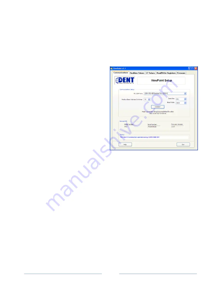
Communications
The
Communications
screen provides the setup
parameters that allow ViewPoint to
communicate with the PowerScout
™
.
PC COM Port
– Enter the port on the computer
connected to the PowerScout. The field
populates using the addresses entered to
function as a drop-down menu.
Modbus Base Address Switches
– Enter the
modbus address set on the PowerScout’s upper
and lower modbus address switches. Available
are modbus addresses from 01 (hex 01) to 254
(hex FE). The 00 setting is reserved for factory
use.
Data Bits
– Default setting is 8N1.
Baud Rate
– Default setting 9600.
Click the
Connect
button to connect ViewPoint
with the PowerScout. The
Device Info
section
of the screen displays the
Model Number
,
Serial Number
and
Firmware Version
of the
PowerScout.
The
Status
window displays communication
messages.
Communication Error
If ViewPoint is unable to communicate with the PowerScout, the
Status
window displays with the
message “Error communicating with meter. Check settings and meter switches.” To resolve this
communications error, try the following:
•
No RS-485 option available in the
PC COM Port
drop-down menu - This indicates the
PowerScout is not properly connected or the required software driver is not installed.
•
Modbus Base Address Switch
does not match the selected upper and lower switch settings on
the PowerScout.
•
The selected Baud Rate does not match the PowerScout’s baud rate.
For more information, refer to Appendix D,
Troubleshooting Communication Issues
.
Summary of Contents for PowerScout 3
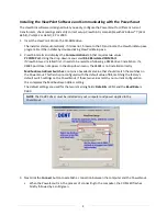
Page 19: ...15 Figure IV 1 Single Phase Two Wire N white L1 black L2 red L3 blue ...
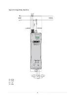
Page 20: ...16 Figure IV 2 Single Phase Three Wire N white L1 black L2 red L3 blue ...
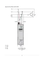
Page 21: ...17 Figure IV 3 Three Phase Three Wire Delta N white L1 black L2 red L3 blue ...
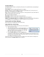
Page 22: ...18 Figure IV 4 Three Phase Four Wire Wye N white L1 black L2 red L3 blue ...
Page 23: ...19 Figure IV 5 Three Phase Four Wire Delta N white L1 black L2 red L3 blue ...


