background image


PowerScout

 Technical Specifications 


Specification 

Description 

Service Type 

Single Phase, Three Phase-Four Wire (WYE), Three Phase-Three Wire (Delta) 

3 Voltage Channels 

CATIII 80-346 Volts AC Line-to-Neutral, 600V Line-to-Line 

Current Channels 

3 channels 0-5,000+ Amps depending on current transducer 

Maximum Current Input 

175% of current transducer rating 

Measurement Type 

True RMS using high-speed digital signal processing (DSP) 

Line Frequency 

50/60/499Hz, DC 

Waveform Sampling 

12 kHz 

Parameter Update Rate 

.5 seconds 

Measurements 

Volts, Amps, kW, kWh, kVAR, kVARh, kVA, kVAh, Apparent Power Factor (aPF), 
Displacement Power Factor (dPF). All parameters for each phase and for system 
total. 

Accuracy 

Better than 1% (<0.5% typical) for V, A, kW, kVAR, kVA, PF 

Resolution 

0.01 Amp, 0.1 Volt, 0.01 watt, 0.0 1 VAR, 0.0 1 VA, 0.01 Power Factor depending on 
scalar setting 

PhaseChek

 Indicators 

Bi-color LEDs (red and green):  1 LED to indicate communication, 3 LEDs for correct 
phasing (Green when voltage and current on the on the same phase; Red when 
incorrectly wired.), 2 LED I/O indicators 

Pulse Output 

Open Collector with 10K ohm pull up to 5V, 75mA max current, 40V max open 
voltage 

Pulse Input 

10K ohm pull-up to 5V, 3mA max input, 100Hz max frequency 

Communication 

  Direct 

Modbus over RS-485 

  Max Length for Modbus 

1200 meters with Data Range of 100K bits/second with 24AWG wire 

  Modbus Framing 

RTU (binary) 

  Communication Rate (baud)  9600 (default), 19200, 57600, 115200 
  Data Bits 

  Parity 

None, Even, Odd 

  Stop Bit 

2, 1, 0 

Data Formats 

Modbus Protocol 

Power 

From L1 Phase to L2 Phase. 80-600VAC CAT III 50/60Hz 70mA Max. Non-user 
replaceable .5 Amp internal fuse protection 

Mechanical 

  Operating Temperature 

7 to + 60 °C (20 to 140 °F) 

  Humidity 

5% to 95% non-condensing 

  Enclosure 

ABS plastic, 94-V0 flammability rating 

  Weight 

326 g (11.5 ounces), exclusive of CTs 

  Dimensions 

44  x 59 x 197 mm (1.7” x  2.3”  x 7.8”) 

ViewPoint™ Minimum System Requirements 

  Operating System 

Windows® 7 (32 or 64 bit), Vista (32 or 64 bit), XP or 2000 

  Communications Port 

One USB port or serial port 

  Hard Drive 

50 MB minimum available 

  Processor 

Pentium Class 1 GHz or more recommended 

Summary of Contents for PowerScout 3

Page 1: ...Operator s Guide PowerScout 3 Power Meter and ViewPoint Software PowerScout 3 v1 3 ViewPoint v2 1 July 2010 ...

Page 2: ...2010 DENT Instruments Inc All rights reserved This manual may not be reproduced or distributed without written permission from DENT Instruments DENT Instruments 64 NW Franklin Avenue Bend Oregon 97701 2906 USA Phone 541 388 4774 Fax 541 385 9333 www DENTinstruments com ...

Page 3: ...cout Setup Using the LEDs 10 SECTION IV FIELD INSTALLATION 12 Mounting the PowerScout 3 12 Connecting the PowerScout 3 12 Completing the Wiring Connections Modbus Voltage Leads and CTs 12 Powering the PowerScout3 13 Setting the Modbus Address 13 Establishing Communication 13 PowerScout 3 Wiring Diagrams 14 SECTION V USING THE VIEWPOINT SOFTWARE 20 Overview of the ViewPoint Screens 20 Communication...

Page 4: ...Emulation 36 Appendix C Installing Firmware Updates for the PowerScout 3 38 Firmware Updates 38 Downloading and Installing Firmware 38 Appendix D Troubleshooting Communication Issues 41 Baud Rate Communications Error 41 Port Error 41 Firmware Update Fails 42 Other Communication Failures 42 Appendix E PowerScout Modbus Register Assignment Tables 43 Modbus Register Assignments 43 Configuration Regis...

Page 5: ...equency and more are derived from the voltage and current inputs The communications interface to the unit is an RS 422 485 serial connection that uses the modbus protocol for sending commands and retrieving data A separate remote terminal unit RTU Data Logger or Building Management and Control System is usually connected to the PowerScout This separate unit provides data recording and trend loggin...

Page 6: ...ing monitored 3 Connect the voltage leads to the different phases Use proper safety equipment gloves and protective clothing as required for the voltages monitored Denotes high voltage Risk of electric shock Life threatening voltages may be present Qualified personnel only DO NOT EXCEED 600V This meter is equipped to monitor loads up to 600V Exceeding this voltage will cause damage to the meter an...

Page 7: ...ion à des phases différentes Utiliser des équipements de sécurité gants et des vêtements de protection qui sont nécessaires pour les tensions surveillées Indique haute tension Risque de choc électrique Hautes tensions peuvent être présentes qui mettent la vie en danger Personnel qualifié uniquement NE PAS DEPASSER 600V Ce compteur peut contrôler les charges jusqu à 600V Le dépassement de cette ten...

Page 8: ...ing Green when voltage and current on the on the same phase Red when incorrectly wired 2 LED I O indicators Pulse Output Open Collector with 10K ohm pull up to 5V 75mA max current 40V max open voltage Pulse Input 10K ohm pull up to 5V 3mA max input 100Hz max frequency Communication Direct Modbus over RS 485 Max Length for Modbus 1200 meters with Data Range of 100K bits second with 24AWG wire Modbu...

Page 9: ...ud Rate is 9600 See Section V Using the ViewPoint Software for additional information about setting the modbus address Set the computer aside 4 Securely mount the PowerScout 3 using the two mounting tabs at each end of the case 5 Mount each current transformer CTs on the wire to be monitored Next connect the CT leads to the terminal block on the PowerScout starting with the lowest voltage first Ve...

Page 10: ...move the RS 485 adapter from the PowerScout Connect the PowerScout to the modbus network 14 Configure the RTU data logging equipment to receive data from the PowerScout For more information on this step consult the instruction manual for RTU data logger PowerScout 3 Diagram Figure II 1 PowerScout 3 Layout US voltage wire colors shown Voltage Leads I O Port Indicator LEDs Terminal Block for I O Por...

Page 11: ...ed into the adapter Refer to figure III 2 for the cable location on the adapter The Found New Hardware Wizard window appears 3 The window states This wizard helps you install software for Model USOPTL4 and asks What do you want the wizard to do 4 Select Install the software automatically and click Next 5 Click Finish when the installation is complete 6 Remove the CD from your computer 7 Verify tha...

Page 12: ...qualifié uniquement To complete the connection between the PowerScout and the computer the three wires coming from the RS 422 485 adapter are plugged into the PowerScout 1 Insert each white ferrule into the appropriate RS 422 485 connection on the PowerScout The red wire inserts in the black wire in and the green wire in GND USB connector port Ferrule connectors Figure III 2 RS 422 485 Adapter Thi...

Page 13: ...rst it needs to be restarted following a RS485 driver installation If a RS485 port does not appear in the drop down menu the RS485 is not installed correctly Modbus Base Address Switches Contains a hexadecimal value that should match the switches on the PowerScout This field is pre configured with the default value of 01 matching the factory s default switch settings on the PowerScout If these two...

Page 14: ...t that simplifies installation by ensuring proper CT to phase installation and avoiding faulty data collection The PowerScout automatically adjusts for CT orientation reducing set up time and nearly eliminating installation errors The PowerScout has three bi color PhaseChek LEDs These LEDs provide the following information All LEDs are green the system power factor is greater than 0 55 and the CTs...

Page 15: ... CT 3 are reversed Switch the position of the CTs flashing red CT 1 and CT 2 are reversed Switch the position of the CTs flashing red CT 1 is swapped with either CT 2 or CT 3 Switch CT 1 with CT 2 or Switch CT 1 with CT 3 CT 2 is swapped with either CT 1 or CT 3 Switch CT 2 with CT 1 or Switch CT 2 with CT 3 CT 3 is swapped with either CT 1 or CT 2 Switch CT 3 with CT 1 or Switch CT 3 with CT 2 CT...

Page 16: ...n S 2 Connect the CTs on the PowerScout connections labeled CT 1 CT 2 and CT 3 Place the CTs on the phase wires of the load to be monitored and corresponding to the phase of the voltage leads The CT labeled CT 1 must be placed on L1 phase voltage wire CT 2 must be on the L2 voltage and CT 3 on the L3 voltage Refer to PhaseChek in Section III for information about the CT LEDs and verifying the CT i...

Page 17: ...hen entered into the RTU or data logger See the Appendix for a hexidecimal conversion table Hexidecimal Address Address Availability 00 Reserved for configuring the communication protocol to 9600 baud 8 bit 1 stop bit and no parity This address can be used if you are unsure of the PowerScout s current communications settings 01 FE Available 01 is the factory default setting FF Reserved for the syn...

Page 18: ...ntion NE PAS DEPASSER UNE PHASE A 600VAC CAT III Une fois terminé fermer le covercle s il y en a un CAUTION THE POWERSCOUT 3 SHOULD ONLY BE WIRED BY QUALIFIED PERSONNEL HAZARDOUS VOLTAGES EXIST ATTENTION LE POWERSCOUT 3 NE DOIT ETRE BRANCHE QUE PAR UN PERSONNEL QUALIFIE TENSIONS DANGEREUSES SONT PRÉSENTES DANGER THE UNENCLOSED POWERSCOUT BOARD REQUIRES EXTRA CAUTION WHEN CONNECTING LIFE THREATENIN...

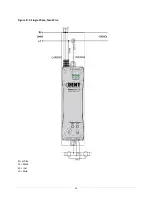
Page 19: ...15 Figure IV 1 Single Phase Two Wire N white L1 black L2 red L3 blue ...

Page 20: ...16 Figure IV 2 Single Phase Three Wire N white L1 black L2 red L3 blue ...

Page 21: ...17 Figure IV 3 Three Phase Three Wire Delta N white L1 black L2 red L3 blue ...

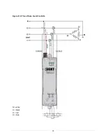
Page 22: ...18 Figure IV 4 Three Phase Four Wire Wye N white L1 black L2 red L3 blue ...

Page 23: ...19 Figure IV 5 Three Phase Four Wire Delta N white L1 black L2 red L3 blue ...

Page 24: ...Baud Rate Default setting 9600 Click the Connect button to connect ViewPoint with the PowerScout The Device Info section of the screen displays the Model Number Serial Number and Firmware Version of the PowerScout The Status window displays communication messages Communication Error If ViewPoint is unable to communicate with the PowerScout the Status window displays with the message Error communic...

Page 25: ...lar A scalar is used to multiply the raw data value to convert information read from the modbus registers Refer to Table III 1 for a list of values Example If the scalar value in register 44602 is set to 3 and the total true power for the system kW is read from modbus register 44003 Offset 4002 and a value of 3465 is returned the true system kW is 3465 X 0 1 346 5 kW CT Type Displays the CT select...

Page 26: ...d Read Write Registers The Read Write Registers screen provides diagnostic and special configuration options allowing the changing or viewing of the value of any PowerScout registers Its use is not required for a basic setup Element The PowerScout 3 is a single meter and cannot be changed from Element A Read Modbus Register Reads a specified modbus register by typing the register address in the bo...

Page 27: ...tes the status of the logger Refer to Appendix E for a list of modbus registers and their descriptions Firmware The Firmware screen verifies the current firmware version and updates the PowerScout 3 internal firmware Element The PowerScout 3 is a single meter and cannot be changed from Element A Firmware Update File The file containing the new firmware version can be entered using the box or locat...

Page 28: ...tarts the installation of the new firmware Communication and Status Messages Refer to Appendix D Troubleshooting Communication Issues Using ViewPoint to Verify Setup ViewPoint can be used to verify the connection setup of the PowerScout 1 Start the ViewPoint software 2 Select the PowerScout settings on the Communications screen and click the Connect button The Status window displays the message PS...

Page 29: ... protocols limits the data registers to a maximum of two bytes 16 bits or a maximum decimal value of 65535 Modbus requires that the data be unsigned positive integer values To overcome these limitations some measured and stored values must be scaled to fit into the modbus registers The raw value read from the modbus registers is multiplied by a scalar to convert the raw data The following table li...

Page 30: ... 1 the following data is used Volts x amps watts 480 volts x 100 amps 48 000 watts Watts x 3 system watts 48 000 watts x 3 144 000 watts 144kW Check the register s value using the data scalar 2 value of 01 System kW scalar value register value 144kW 01 14 400 Since 14 400 is less than 65 535 using data scalar 2 is a good choice for this example For example 2 the following data is used 480 volts x ...

Page 31: ...rol Pulse Input Pulse input is used to count accumulate and scale pulses received from non DENT external pulse initiating meters such as gas water or other electrical meters The PowerScout 3 can detect digital signals dry contacts of minimum 10 milliseconds in duration The green LED will stay on while the pins are shorted together When the port is used as an input the green LED is lit when the por...

Page 32: ...pulse LSW 45102 5101 I O port 1 pulse input accumulator MSW Scaled pulse MSW 45103 5102 I O port 1 pulse input scaling integer Integer scale factor Scale 45103 45104 1000 45104 5103 I O port 1 pulse input scaling decimal x1000 decimal fraction of scale factor Table VI 3 I O Port 1 Pulse Input Modbus Register Offset Register Name Detailed Description 44401 4400 I O port 2 status 0 input LOW switch ...

Page 33: ...rt 2 output control 0 output LOW closed 1 output HIGH open Register is set to default 1 if Pulse Input 2 Configuration or Pulse Output 2 Configuration registers are not 0 45210 5209 Configures the pulse output for I O port 2 0 no pulse output kWh kVARh or kVAh Register number 45211 5210 Port 2 pulse output relay type 0 normally open HIGH 1 normally closed LOW Table VI 6 I O Port 2 Pulse Output Loc...

Page 34: ...he protocol standard used by the PowerScout as the hardware s serial interface while modbus is the communication protocol Daisy Chain Layout for RS 485 Network When multiple devices are connected to a single modbus master device the multiple devices need to be connected in a daisy chain A daisy chain means that all plus connections are chained together and all minus connections are chained togethe...

Page 35: ...power to the unit How many PowerScout 3 instruments can be connected together Up to 254 PowerScout 3 meters can be connected together How is hexadecimal HEX to decimal converted Use the Hexadecimal to Decimal conversion table in the Appendix section of this manual What is true RMS RMS stands for Root Mean Square True RMS is the AC voltage current that will produce the equivalent amount of heat in ...

Page 36: ...icant Word Unit of data with the high order bytes at the left PhaseChek PhaseChek is a unique feature of the PowerScout and greatly simplifies installation and at a glance verifies correct CT orientation during installation The PowerScout automatically adjusts for CT orientation greatly reducing set up time and all but eliminating installation errors It is common for an individual phase power fact...

Page 37: ...d control system or SCADA system by transmitting telemetry data to the system and or altering the state of connected objects based on control messages received from the system SCADA SCADA stands for Supervisory Control And Data Acquisition It generally refers to an industrial control system a computer system monitoring and controlling a process ...

Page 38: ...2 141 8D 184 B8 227 E3 13 0D 56 38 99 63 142 8E 185 B9 228 E4 14 0E 57 39 100 64 143 8F 186 BA 229 E5 15 0F 58 3A 101 65 144 90 187 BB 230 E6 16 10 59 3B 102 66 145 91 188 BC 231 E7 17 11 60 3C 103 67 146 92 189 BD 232 E8 18 12 61 3D 104 68 147 93 190 BE 233 E9 19 13 62 3E 105 69 148 94 191 BF 234 EA 20 14 63 3F 106 6A 149 95 192 C0 235 EB 21 15 64 40 107 6B 150 96 193 C1 236 EC 22 16 65 41 108 6C...

Page 39: ...imal Hex Decimal Hex 39 27 82 52 125 7D 168 A8 211 D3 254 FE 40 28 83 53 126 7E 169 A9 212 D4 255 41 29 84 54 127 7F 170 AA 213 D5 42 2A 85 55 128 80 171 AB 214 D6 43 2B 86 56 129 81 172 AC 215 D7 Table Appendix A 1 Decimal to Hexadecimal Conversion Table ...

Page 40: ...Modbus CT value Amp The following is an example command with CT set for 100A 91hFFhVeris H8036 0100 2 Full Data Modbus 100 Amp Example command explanation 91h version control FFh standard for active The 91h and FFh are 4 bytes in front of the string that are not displayed in the RTU CT Amperage Rating Veris Model Number CT 100A Veris Type H8036 0100 2 CT Value 100A 100A CT 300A Veris Type H8036 03...

Page 41: ...3 12 Apparent PF L1 Individual Phase Apparent Power Factors PF 3 values 40014 13 Apparent PF L2 40015 14 Apparent PF L3 40016 15 Volts L1 to L2 Individual Phase to Phase Voltages Volts Delta 3 values 40017 16 Volts L2 to L3 40018 17 Volts L1 to L3 40019 18 Volts L1 to Neutral Individual Phase to Neutral Voltages Volts Wye 3 values 40020 19 Volts L2 to Neutral 40021 20 Volts L3 to Neutral 40022 21 ...

Page 42: ...g only two CTs Previous firmware versions required three CTs to measure a delta load The enhanced I O operation allows direct I O control status The control setting is stored for initializing during a power cycle Multiple register reading is enhanced using a single modbus command 03 Read Holding Registers The registers are not changed until the command is complete Downloading and Installing Firmwa...

Page 43: ...e Firmware tab in ViewPoint Click Browse to locate the extracted firmware files Click Update to start the firmware update 5 When the update completes ViewPoint displays a message window confirming a successful update ...

Page 44: ...ng the I O LED on for unused I O does not affect meter operation There are two methods available to turn off the LED Only one method needs to be completed Method 1 Set the control output to disable the LED Set register 44402 1 for I O 1 44403 1 for I O 2 Wait 60 seconds before power cycling the PowerScout 3 to save the settings Method 2 Enable input pulse counting Set register 45100 1 for I O 1 45...

Page 45: ...switches to 0 3 Press the Connect button With both settings at 00 ViewPoint and the PowerScout will communicate at a 9600 baud rate regardless of a baud rate mismatch Communications is established 4 Next select the desired baud rate in ViewPoint from the Baud Rate drop down menu This synchronizes the baud rates between ViewPoint and the PowerScout 5 Click Connect to reconfirm communications Port E...

Page 46: ...ems can also cause a communication failure Check for wiring and cabling issues with the RS 485 adapter Check for polarity frayed wires and or pinched insulation Verify that the dip switches on the back of the USB to RS 422 485 adapter are set to the following Reboot the computer Click Connect on the Communications tab to reestablish communications ...

Page 47: ...arent Power kVA 44014 4013 Displacement PF System System Total Power Factor PF 44015 4014 Apparent PF System System Total Power Factor PF 44016 4015 Amps System Avg Total current in all phases 44017 4016 Volts Line to Line Avg Voltage Line to line Volts Average 44018 4017 Volts Line to Neutral Avg Voltage Line to neutral volts Average 44019 4018 Volts L1 to L2 Individual Phase to Phase Voltages 44...

Page 48: ...Demand kW resettable It displays the default value after a CAM until 1 demand window elapses After a power cycle or CPU reset the value is not reset but it does not update again until 1 demand window elapses 44082 4081 kVA Demand System Max System Maximum Instantaneous kVA Demand kVA resettable It displays the default value after a CAM until 1 demand window elapses After a power cycle or CPU reset...

Page 49: ...ze Register Multiple PowerScout s synchronization register 44066 4065 Clear Accumulated Measurements Writing 1234 resets all C registers accumulated PowerScout data kWh kWh etc stored in flash to CAM Default value Non Writable Registers Modbus Offset Register Description 44201 4200 Model Number 1 st 2 bytes Model Name 10 bytes ASCII Alpha Numeric 44202 4201 Model 2 44203 4202 Model 3 44204 4203 Mo...

Page 50: ... System System Positive Displacement Power Factor dPF Register is 100x actual value If the System dPF 44014 is positive this register will contain that value else it will be zero 46015 6014 Positive Apparent PF System System Positive Apparent Power Factor aPF Register is 100x actual value If the System aPF 44015 is positive this register will contain that value else it will be zero 46023 6022 Posi...

Page 51: ...tem Negative True Energy LSW kWh resettable 47002 7001 Negative kWh System MSW System Negative True Energy MSW kWh resettable 47003 7002 Negative kW System System Negative Instantaneous Negative True Power kW net sum of all individual kWs if sum is positive value 0 47006 7005 Negative kW System Max System Highest Instantaneous Negative Draw Since Reset kW resettable 47007 7006 Negative kW System M...

Page 52: ...ARh L2 MSW 47036 7035 Negative kVARh L3 LSW 47037 7036 Negative kVARh L3 MSW 47038 7037 Negative kVAR L1 Individual Phase Negative Instantaneous Reactive Powers kVAR 47039 7038 Negative kVAR L2 47040 7039 Negative kVAR L3 47050 7049 Negative Displacement PF L1 Individual Phase Negative Displacement Power Factors dPF Register is 100x actual value If the Individual dPF 44050 is Negative this registe...

Page 53: ...rScout This must be different for each PowerScout on a single modbus network The register s high order and low order bits are the 16 bit value of a single or first register to be accessed for a read or write The CRC is the 16 bit CRC value Note that the CRC s LSB and MSB are reversed in comparison to those for the registers and data Read Holding Registers This command reads the contents of a conti...

Page 54: ... bytes were read from the requested register 000C The value of the registers read was 0000 The CRC value was 4070 The number of registers read must be between 1 and 125 inclusive Write Single Register This command writes to a single holding register of the PowerScout The normal response is an echo of the request returned after the register contents are written Command Information Command Layout Ex...

Page 55: ...rite low order bits 00 Register value written low order bits 00 CRC low order bits 8C CRC low order bits 8C CRC high order bits 5C CRC high order bits 5C Table F 5 Format for Modbus Command 03 Command 3706000000018C5C Response 3706000000018C5C The response is from the PowerScout at address 37 One byte was written to at the requested register 0000 The value written was 0000 The CRC value was 5C8C A...

Page 56: ... data Table F 7 Format for Modbus Command 11 17 in decimal Slave ID The PowerScout uses the following default format for the slave ID 00hFFhDENT Instruments PowerScout 3 Serial Number FW Rev Major Revision Minor Revision Scalar X Example 00hFFhDENT Instruments PowerScout 3 PS3912001 FW Rev 1 0 Scalar 3 The 00h is used for version control and the FFh indicates the meter is active The 00h and FFh ar...

Reviews: