6.15.21 0097-445 Rev. C 1 of 1
6200 NE Cherry Drive, Hillsboro, OR 97124 USA
(TF)
800 . 423 . 3555 (T) 503 . 640 . 3012 (
F)
503 . 693 . 9715
DTE OREGON, INC.
DENTALEZ.COM
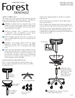
6187 ASSISTANT’S COMFORT STOOL
STEP 1:
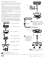
Insert casters (wheels) into base. Apply a significant
amount of pressure to ensure casters are seated properly
(FIG. 1-2).
STEP 2:
Insert height adjustment cylinder into base (FIG. 3).
STEP 3:
Slide adjustable footring over height adjustment
cylinder and tighten footring knob to secure in place (FIG. 4).
STEP 4:
Slide chrome arm tube on top of height adjustment
cylinder until firmly seated (FIG. 5).
STEP 5:
Place the seat assembly on top of height adjustment
cylinder (FIG. 6).
STEP 6:
Remove black plug and insert back assembly into
seat assembly. Replace black plug after installation (FIG. 7).
STEP 7:
Slide ratcheting arm into arm tube. Firmly tighten arm
tube knob clockwise to secure arm in place (FIG. 8).
STEP 8:
Sit on stool to permanently lock cylinder into base
and seat. At this time, the piston in the height adjustment
cylinder may be engaged by activating the seat height lever
to adjust seat location.
FIG. 6: SEAT ASSEMBLY
FIG. 7: BACKREST ASSEMBLY
FIG. 8: RATCHETING ARM
FIG. 4: ADJUSTABLE FOOTRING
FIG. 5: CHROME ARM TUBE
FIG. 2: ALUMINUM BASE
FIG. 1: CASTERS (WHEELS)
FIG. 3: HEIGHT ADJUSTMENT
CYLINDER
WARNING: When
inserting the height
adjustment cylinder,
care should be
exercised to avoid
pinching fingers.
WARNING: Assure arm tube and
footring adjustment knobs are
tightened (by turning clockwise)
to prevent any slippage that
could result in injury.
WARNING: Be sure casters are firmly
seated before using stool.
FOOTRING KNOB
BLACK PLUG
ARM TUBE
KNOB


