background image

Guidance and manufacturer's declaration - Electromagnetic Immunity

The product is intended for use in the electromagnetic environment specified below. The customer or the user of the product should assure that it is used in 
such an environment.

NOTE1:  At 80MHz and 800MHz, the higher frequency range applies.
NOTE2:  These guidelines may not apply in all situations. Electromagnetic propagation is affected by absorption and reflection from structures, objects and people.

a: Field strengths from fixed transmitters, such as base stations for radio (cellular/cordless) telephones and land mobile radios, amateur radio, AM and FM 

radio broadcast and TV broadcast cannot be predicted theoretically with accuracy. To assess the electromagnetic environment due to fixed RF transmitters, 
an electromagnetic site survey should be considered. If the measured field strength in the location in which the product is used exceeds the applicable RF 
compliance level stated above, the product should be observed to verify normal operation. If abnormal performance is observed, additional measures may 
be necessary, such as reorienting or relocating the product.

b: Over the frequency range 150kHz to 80MHz, the field strength should be less than 3V/m.

Immunity test

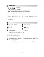
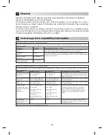
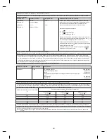
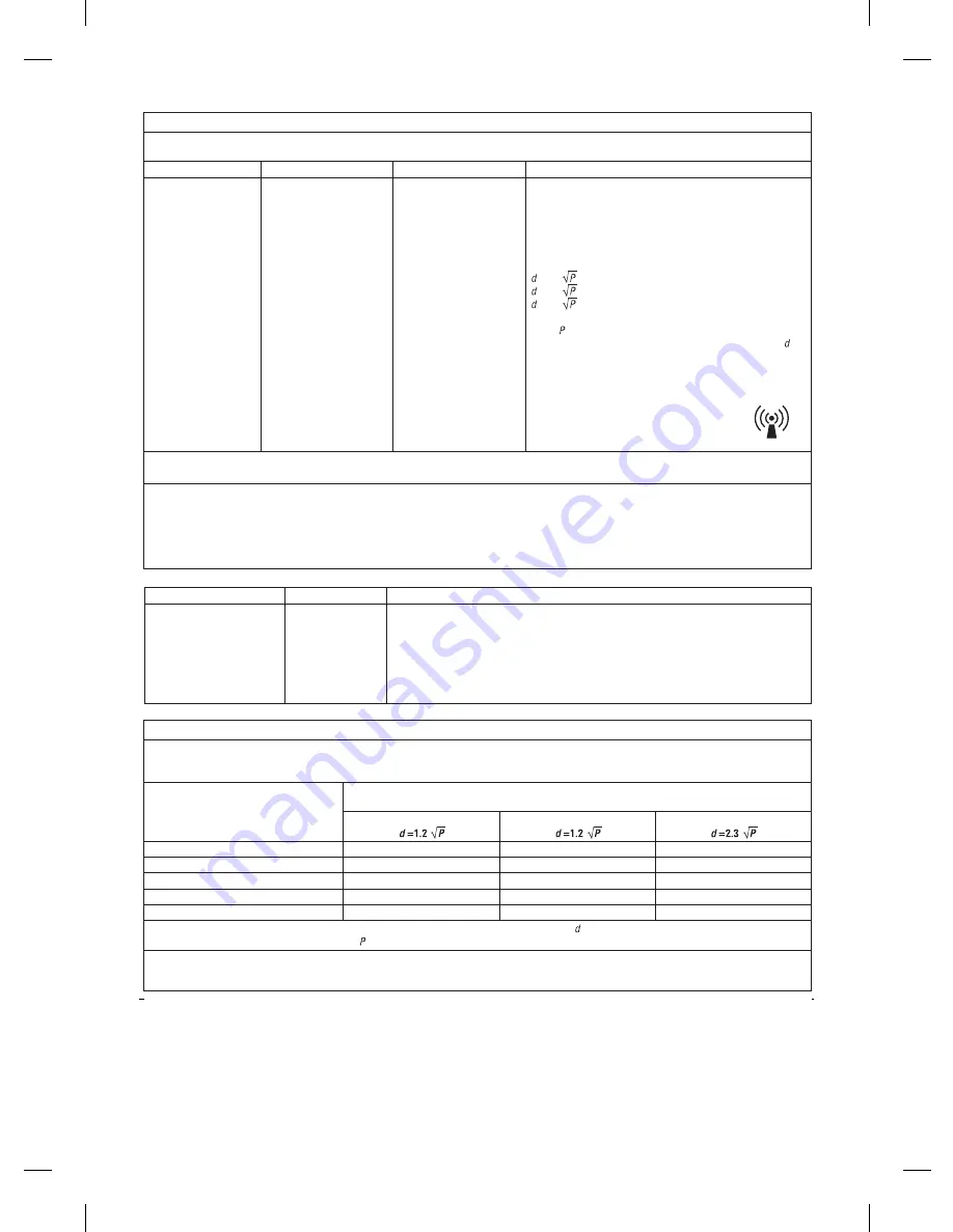
IEC60601 test level

Electromagnetic environment - guidance

Conducted RF
IEC61000-4-6

Radiated RF
IEC61000-4-3

3Vrms
150kHz to 80MHz

3V/m
80MHz to 2.5GHz

Compliance level
3 Vrms

3 V/m

Portable and mobile RF communications equipment should be 
used no closer to any part of the product, including cables, than 
the recommended separation distance calculated from the 
equation applicable to the frequency of the transmitter.

Recommended separation distance

   = 1.2    
   = 1.2       80MHz to 800MHz
   = 2.3       800MHz to 2.5GHz

Where    is the maximum output power rating of the transmitter 
in watts (W) according to the transmitter manufacturer, and (  ) is 
the recommended separation distance in meters (m).

Field strengths from fixed RF transmitters as determined by an 
electromagnetic site survey(a) should be less than the compliance 
level in each frequency range(b).
Interference may occur in the vicinity of equipment 
marked with the following symbol: 

Complies with

Maximum length

Cables and accessories

RF emissions, CISPR11
Electrostatic discharge (ESD):
Surge:
Voltage dips, short interruptions and voltage variations on power supply input 
lines:
Conducted RF:
Radiated RF:

1.8m

AC adaptor

Class B/Group 1

IEC61000-4-2
IEC61000-4-5

IEC61000-4-11

IEC 61000-4-6

IEC61000-4-3

150kHz to 80MHz

Recommended separation distances between portable and mobile RF communications equipment and the product

The product is intended for use in an electromagnetic environment in which radiated RF disturbances are controlled. The customer or the user of the product 
can help prevent electromagnetic interference by maintaining a minimum distance between portable and mobile RF communications equipment (transmitters) 
and the product as recommended below, according to the maximum output power of the communications equipment.

For transmitters rated at a maximum output power not listed above, the recommended separation distance ‘  ’ in meters (m) can be estimated using the equation 
applicable to the frequency of the transmitter, where ‘  ’ is the maximum output power rating of the transmitter in watts (W) according to the transmitter manufacturer.

Rated maximum output power of transmitter

W

800MHz to 2.5GHz

80MHz to 800MHz

NOTE1: At 80MHz and 800MHz, the higher frequency range applies.
NOTE2: These guidelines may not apply in all situations. Electromagnetic propagation is affected by absorption and reflection from structures, objects and

            people.

Separation distance according to frequency of transmitter

m

0.01

0.1

1

10

100

0.12
0.38

1.2
3.8

12

0.12
0.38

1.2
3.8

12

0.23
0.73

2.3
7.3

23

16

Summary of Contents for istar

Page 1: ...OM EZ721E ...

Page 2: ......

Page 3: ... AC Adapter Plug Head 10 9 Periodic Maintenance 11 10 Overload Protection 11 11 Troubleshooting 12 12 Specifications 12 13 Classification 13 14 Symbols 13 15 Warranty 14 16 Spare Parts 14 17 Disposal 15 18 Electromagnetic Compatibility Information 15 French 17 User and Indications for Use Do not use this product in the vicinity of explosive substances and flammable materials It is the responsibili...

Page 4: ... your Authorized StarDental Dealer for service Using the handpiece under these abnormal conditions may cause injury or damage to property Should battery fluid leak and get into patient s or user s eyes immediately flush eyes thoroughly with clean water and seek medical attention If left untreated this condition may result in blindness Do not charge use or store the product in direct sunlight a veh...

Page 5: ...ospitals and for visiting dental professionals Read this Operation Manual before use to fully understand the product functions Always consider the safety of the patient when operating this product Connect or disconnect the disposable prophy angle only after rotation of the handpiece has completely stopped This may cause injury or cause damage to the connecting portion of the disposable handpiece D...

Page 6: ...e install the AC adapter in such a way that it can be quickly disconnected from the outlet in an emergency Do not place any object within 6 inches of the AC adapter When disconnecting the AC adapter be sure to hold the adapter body Disconnecting by pulling on the cord may damage the cord Refer to the disposable prophy angle operation manual for the specific disposable prophy angle being used for h...

Page 7: ...5 1 Package Contents Set components Product name Quantity 1 Handpiece motor 1 2 Stand 1 3 AC adapter 1 4 Handpiece sleeve 100pcs 1 iStar ...

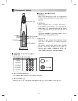
Page 8: ...otor and pressing it again stops the rotation Alternate operation Alternatively pressing and holding down the ON OFF key rotates the handpiece motor while the button is being pressed Releasing the ON OFF key stops rotation Temporary rotating operation Indicators on operation panel A SPEED lamp The speed is indicated by lamps B Battery charge indicator This indicator lamp lights up during battery c...

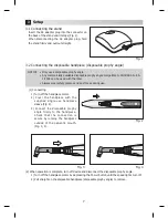
Page 9: ...ar Always wear safety glasses and dust mask during use 1 Connecting 1 Turn off the handpiece motor 2 Cover the handpiece with the supplied single use handpiece sleeve Fig 2 3 Connect the disposable prophy angle firmly to the handpiece Check that the connection is secure by running the handpiece outside of the patient s mouth Fig 3 4 2 When operation is complete turn off device and disconnect the d...

Page 10: ...ce may also be damaged if dropped Remove the handpiece sleeve from the handpiece motor before placing it on the battery charger The handpiece battery charging stand is exclusively for the iStar handpiece motor Never use the stand for any other purpose The battery will get warm during charging but this is not a failure Inserting or removing the plug at short intervals approx 5 minutes may generate ...

Page 11: ...attery voltage However the low voltage may not be immediately detected if the product is left under the low voltage condition before turning on the power This is due to the properties of the battery and is not a failure 5 2 Power supply Press and hold down the POWER key to turn on the power The SPEED lamp will light up on the operation panel 5 3 SPEED Setting Speed is adjusted by pressing the SPEE...

Page 12: ... every patient by wiping down with isopropyl alcohol solution Wipe all surfaces including the chuck buttons and bottom charge area as all of these locations may become contaminated during use Compliance with cleaning procedures is critical to patient safety Do not lubricate the handpiece motor Do not use any solvents such as benzene or thinner to clean the handpiece motor This product cannot be st...

Page 13: ...display an error code on the display When an error is displayed turn the power off and on again to check whether the error persists If the error is displayed again follow the solutions recommended in the table below Item Error display Error description Cause Check and remedy During rotation The SPEED lamp flashes Outside the range of working temperatures The use temperature is significantly low Us...

Page 14: ... condensation The temperature of the battery pack is high The battery is not charged when the temperature of the battery pack is approx 40 C 104 F or higher Charge the rechargeable battery within permissible temperatures Handpiece motor stand AC adapter Trouble Cause Remedy The motor does not rotate The handpiece motor has an internal failure Contact your Authorized StarDental Dealer Short circuit...

Page 15: ...n 13 14 Symbols Consult operation instructions Class II equipment Type B applied part Caution Refer to attached instructions Direct Current Alternate Current For indoor use only Efficiency Level TUV Certification Mark Do not reuse Marking on the outside of Equipment or Equipment parts that include RF transmitters or that apply RF electromagnetic energy for diagnosis or treatment This product meets...

Page 16: ...NY WAY OR TO GRANT ANY OTHER WARRANTY Provided conditions in warranty are met warranty Registration Please visit one of the websites below to register your StarDental product This will ensure proper registration and prompt and accurate service should any of your purchases need evaluation or repair during the warranty period For Identafi Oral Cancer Screening System products www identafi net warran...

Page 17: ...The product is intended for use in the electromagnetic environment specified below The customer or the user of the product should assure that it is used in such an environment NOTE Ut is the AC mains voltage prior to application of the test level Immunity test IEC60601 test level Electromagnetic environment guidance Electrostatic discharge ESD IEC61000 4 2 Electrical fast transient burst IEC61000 ...

Page 18: ...e transmitter in watts W according to the transmitter manufacturer and is the recommended separation distance in meters m Field strengths from fixed RF transmitters as determined by an electromagnetic site survey a should be less than the compliance level in each frequency range b Interference may occur in the vicinity of equipment marked with the following symbol Complies with Maximum length Cabl...

Page 19: ......

Page 20: ...C 2015 10 20 ...

Reviews: