background image

Step by Step Instructions

19

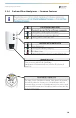
5 .3 .4  Pack and Flow Handpieces — Common Features

These features are common to both handpieces. For features exclusive to 
each handpiece, see 

5 .3 .4 .1 Pack Handpiece Features

 and 

5 .3 .4 .2 Flow 

Handpiece Features .

.

COLOR AND MATERIALS

JULY 31, 2017

VER.

DATE

NOTES

1

INITIAL RELEASE

7-24-17

2

- UPDATE BLUE COLOR SPEC.

- CHANGE TO NEW LOGO.

7-31-17

SHEET 1 of 4

VDW WANDS-2

-  UPDATE ICONS TO MATCH 

   X-SMART

A

GLOSS WHITE

ABS

A

A

B

B

D

F

F

F

F

G

C

C

E

G

H

H

I

I

G

BLUE TBD

PAD PRINT

F

BLK, BLUE, YELLOW

ULTEM

D

BLACK

PEEK

C

TRANS. WHITE

ABS

B

MEDIUM GRAY

SANTOPRENE

H

GRAY

PAD PRINT

B

B

MATCHED TO X-SMART

IN PROCESS

IN PROCESS

OEM RESIN, MACHINED

SAME AS EXISTING 

CALAMUS

I

GRAY

LASER MARKED

REF AEU-65

SN EN19000719-001

REF AEU-65-DS XXXX

SN XX19000719-001

REF AEU-65

SN EN19000719-001

REF AEU-65

SN EN19000719-001

10mm

12mm

ENLARGED FOR 

CLARITY.

CONTENT TBD

E

GLOSS WHITE

ULTEM

IN PROCESS.

POSSIBLE MINOR COLOR 

VARIATION

MATCHED TO X-SMART

CONTENT TBD

22mm

22mm

VDW LOGO

PANTONE (PMS) 7684C

CMYK 100/45/0/18

RGB 0/97/161

PANTONE (PMS) 425

SAME AS ON DS 

LIGHT GRAY RAL DESIGN

000 75 00

GP

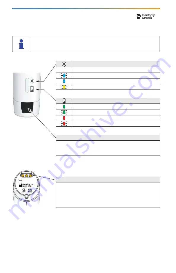
BLUETOOTH INDICATOR

Bluetooth reserved for future firmware upgrades

Flashing blue:

 Searching for connection

Blue:

 Bluetooth connection established

Flashing yellow:

 Connection lost

BATTERY LEVEL INDICATOR

Green:

 Battery full

Flashing green:

 Battery charging

Red:

 Battery low

Flashing Red:

 Battery very low. Charge immediately.

POWER BUTTON

Press to turn on and off the handpiece. 
Handpieces will automatically turn off after 20 minutes of 
inactivity.

ELECTRICAL CONTACTS

The base of each handpiece contains three electrical contacts. 
Periodically clean the contacts on the handpieces and the 
corresponding contacts in the base station with a cotton swab 
to ensure reliable operation. Handpiece serial numbers are also 
located on the bases.

Summary of Contents for Gutta-Smart

Page 1: ...Gutta Smart Directions for Use EN...

Page 2: ...1 Attaching Electric Heat Plugger EHP to Pack Handpiece 13 5 3 2 2 Attaching Thermal Response Tip TRT to Pack Handpiece 13 5 3 2 3 Attaching Heater and GP cartridge to Flow Handpiece 14 5 3 3 Programm...

Page 3: ...5 3 5 4 Replacing the Flow Gutta Percha GP Cartridge 23 6 Cleaning Disinfection and Sterilization 24 6 1 Forward 24 6 2 Base Station 24 6 3 Handpieces 24 6 4 Electric Heat Pluggers EHP Thermal Respons...

Page 4: ...or despite all efforts to do so We would appreciate your feedback in this area If any errors are noted please con tact Dentsply Sirona at the address shown on the back cover page of this manual Dentsp...

Page 5: ...pt the operation of equipment in the vicinity If this happens the interference should be reduced by reorienting or repositioning the device or by screening off the immediate environment The electromag...

Page 6: ...expiration date Dispose of gutta percha cartridges in a sharps receptacle Cleaning Disinfection and Sterilization Do not use a disinfection solution for sterilization of gutta percha cartridges This e...

Page 7: ...ust be met Defective devices can also be transported by air freight or land freight in the original packaging If the battery is defective the device must not be transport ed by air freight under any c...

Page 8: ...a sufficient battery charge before starting treatment Do not place the handpieces charging base or gutta percha cartridges in an autoclave unit or washer disinfector Chemclaving is not recommended fo...

Page 9: ...e exact contents of the package See 5 2 Package Contents 5 1 Document Symbols and Abbreviations Symbol Identification 132 C xxx C Consult instructions for use WARNING Serious injury or death may resul...

Page 10: ...the accessories from their packaging and place them on a flat surface B Check that the device is supplied with all the components listed below Flow Handpiece Base Station Pack Handpiece Power Adapter...

Page 11: ...65 SN EN19000719 001 GP EU 65 9000719 001 U 65 000719 001 Flow Heater HTR Getting Started Guide Directions For Use Pack Handpiece Front end Sealing Cap Save for cleaning procedure Flow Handpiece Fron...

Page 12: ...il the green LEDs on the handpieces stop flashing indicating a full charge Either handpiece can be placed into either side of the base station The left and right base station sockets are interchangeab...

Page 13: ...ny one of 4 orientations C To remove the EHP wait for it to cool down then pull straight out from hand piece 5 3 2 2 Attaching Thermal Response Tip TRT to Pack Handpiece Step Action A Push the TRT int...

Page 14: ...nnula to the desired angle using the cannula bending tool Using fingers or any other device other than the cannula bending tool to curve the cannula can result in GP cartridge rupture or handpiece dam...

Page 15: ...tation you must press the side of the touch screen directly below the handpiece you want to program to access the settings for that handpiece For example if you want to program the handpiece on the le...

Page 16: ...and Indicators Handpiece Battery Level If an EHP or TRT is installed and working properly this icon appears If no EHP or TRT is installed or not working properly this icon appears Setting the temperat...

Page 17: ...al Response Tip TRT to Pack Handpiece C Press the temperature segment of the touch screen then use the button that appears to adjust the temperature to 90 C to activate the TRT mode for the pack handp...

Page 18: ...ed to be on the left side of the base station in the following illustration of the touch screen Flow Handpiece Settings and Indicators Press here to adjust the GP flow temperature 130 160 C using the...

Page 19: ...ROCESS POSSIBLE MINOR COLOR VARIATION MATCHED TO X SMART CONTENT TBD 22mm VDW LOGO PANTONE PMS 7684C CMYK 100 45 0 18 RGB 0 97 161 PANTONE PMS 425 SAME AS ON DS LIGHT GRAY RAL DESIGN 000 75 00 GP BLUE...

Page 20: ...nuous heating Release and press the cuff switch again to continue heating OR CUFF SWITCH TRT MODE Temperature setting 90 C Press and hold the raised ridge on the cuff switch to heat the TRT The heater...

Page 21: ...rve battery power With HTR at set temperature press and hold to extrude GP With no HTR installed press to interrupt GP push rod retrac tion Each additional press alternates the push rod direction if n...

Page 22: ...sec onds at a time You will hear a high frequency tone while the tip is heating then a low frequency tone once the set temperature is reached Release and press the cuff switch again if the heat cycle...

Page 23: ...dle into the canal G Place the heated tip of the cannula against the previously packed GP for 5 seconds H Hold the handpiece lightly when expressing material to allow the device to readily back out of...

Page 24: ...irements for cleaning disinfection and sterilization Observe the concentration of the cleaning or disin fecting solution stated by the manufacturer Failure to adhere to the following instructions or b...

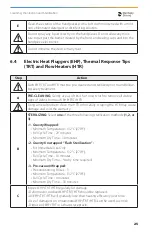
Page 25: ...h EHP TRT HTR Using a metal probe to clean the HTR or forcefully scraping the HTR may cause damage and void the warranty B STERILIZING Select one of the three following sterilization methods 1 2 or 3...

Page 26: ...y Do not immerse GP cartridges into any liquid Do not use GP cartridges after the expiration date Dispose of GP cartridges in a sharps receptacle GP cartridges cannot be reheated or reused Reheating o...

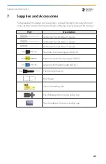
Page 27: ...OLOR AND MATERIALS JULY 24 2017 REF AEU 65 SN EN19000719 001 REF AEU 65 SN EN19000719 001 Medium electric heat plugger 50 05 COLOR AND MATERIALS JULY 24 2017 REF AEU 65 SN EN19000719 001 REF AEU 65 SN...

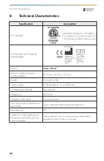
Page 28: ...Length x Height x Width 237 mm x 147 mm x 133 mm Weight 1 46 kg 3 22 lb Power supply LiFePO4 Battery 3 2 V 1500 mAh Charger power adapter 100 240 VAC Frequency 50 60 Hz Charger current input 0 6 A ma...

Page 29: ...ical device class U S A Class I regulation 872 4200 Europe Class 2A rule 9 Transport and storage condi tions Ambient temperature 20 C 50 C 4 F 122 F 132 C xxx C P 20 C 4 F 50 C 122 F Relative humidity...

Page 30: ...SPR 11 Class A Gutta Smart is suitable for use in all estab lishments other than domestic and may be used in domestic establishments and those directly connected to the public low voltage power supply...

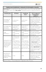
Page 31: ...tial mode 2 kV common mode 1 kV differential mode 2 kV common mode Mains power quality should be that of a typical commercial or hospital environment Voltage dips short interruptions and voltage varia...

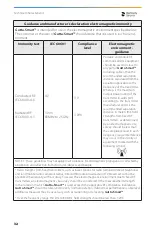
Page 32: ...rmined by an electromagnetic site survey should be less than the compliance level in each frequency range Interference may occur in the vicinity of equipment marked with the following symbol NOTE 1 Th...

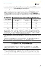
Page 33: ...ve the recommended separation distance d in meters m can be estimated using the equation applicable to the frequency of the transmitter where P is the maximum output power rating of the trans mitter i...

Page 34: ...due to GP deposits around the cartridge Break off the cannula at the cartridge by bending it back and forth with your fingers then use the handle of a wooden cotton swab to push the cartridge out of...

Page 35: ...d not the EHP TRT HTR or accessories included with the Gutta Smart 0 cost for the first return Additional returns will incur a 99 service fee Dentsply Sirona reserves the right to replace 2nd year ret...

Page 36: ...the dis posal of end of life electrical equipment and batteries Make sure the product or battery is not mixed with other types of waste when it is being disposed of Prior to disassembly and disposal...

Page 37: ...anufacturer SN REF 132 C Class II equipment per IEC 60417 5172 SN REF 132 C Type BF applied part per IEC 60417 5333 U S A federal law restricts this device to sale by or on the order of a dentist SN R...

Page 38: ...ntents gutta percha GP Ag AI Cartridge cannula silver GP Ag AI Cartridge capsule aluminum Bluetooth Handpiece temperature Thermal response tip mode Gutta percha flow rate Battery level base station Ba...

Page 39: ...39...
Page 40: ...800 662 1202 Email contact dentsplysirona com Fax 1 800 597 2778 Web dentsplysirona com Outside U S A and Canada Dentsply Sirona Address Maillefer Instruments Holding Sa Chemin du Verger 3 CH 1338 Bal...

Reviews: