background image

63 69 149 D3561

D3561

.

076.01.07

.

02 02.2017

121

Dentsply Sirona 

7 Replacing components

Service Manual Sinius / Sinius CS / Sinius TS

7.1 Removing the cover

båÖäáëÜ

7.1.7.2

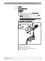
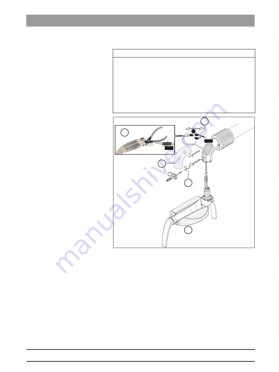
Removing LEDview S parts

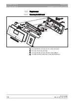
1. Pry off the cover (A).
2. Cut open the cable tie (B).
3. Unplug connector X1 (C).
4. Unscrew the screw and remove the DU cover (D).
5. Remove the LEDview (E).

IMPORTANT

Data backup
➢ Perform a treatment center data backup before replacing the 

lighting system (with NLV or HLV board).

➢ Check the global software version of the treatment center after 

replacing the lighting system.

If necessary, update the global software version and then restore 

the data of the NLV or HLV board.

You can find information on how to perform the data backup and the 

software update in the "DUMC Service Manual".

1.

X1

L225

L225

E

B

A

C

D

Summary of Contents for SINIUS

Page 1: ...New as of Service Manual 02 2017 Sinius Sinius CS Sinius TS English Sinius Service Manual...

Page 2: ...63 69 149 D3561 2 D3561 076 01 07 02 02 2017 Dentsply Sirona Service Manual Sinius Sinius CS Sinius TS...

Page 3: ...ession 10 2 7 Operating the treatment center with HELIODENT Plus unit model 10 3 Prerequisites 11 4 Technical data 12 4 1 Operating transport and storage conditions 14 4 2 Weight and packaging 15 5 Im...

Page 4: ...lement 58 6 3 1 NAJm board Dentist element control 58 6 3 2 HAC board BL motor control 62 6 3 3 NAC board BL motor control 64 6 3 4 NAA board Apex locator 67 6 3 5 HAP1 board Baseboard user interface...

Page 5: ...cope 112 7 1 4 1 Removing the NAR board 112 7 1 5 Assistant element 113 7 1 5 1 Removing the cover on the support arm 113 7 1 5 2 Opening the assistant element 114 7 1 6 Water unit 115 7 1 6 1 Removin...

Page 6: ...rakes on the support arm and dentist element 149 9 1 1 Setting brakes on the SINIUS support arm 149 9 1 2 Set the brakes on the SINIUS SINIUS TS dentist element head 149 9 1 3 Adjusting the brakes on...

Page 7: ...ER An imminent danger that could result in serious bodily injury or death WARNING A possible dangerous situation that could result in serious bodily injury or death CAUTION A possible dangerous situat...

Page 8: ...ment Dentsply Sirona 1 3 Symbols Service Manual Sinius Sinius CS Sinius TS 1 3 Symbols Sinius dentist element Sinius CS dentist element Sinius TS dentist element Sinius assistant element Foot control...

Page 9: ...tion system DUMC Dental Unit Management Console PC program for service support EBL Extended bootloader PCB Printed circuit board board FS Foot control GND Ground HW Hardware L Line LED Light emitting...

Page 10: ...63 69 149 D3561 9 D3561 076 01 07 02 02 2017 1 Structure of the document Dentsply Sirona 1 4 Abbreviations Service Manual Sinius Sinius CS Sinius TS...

Page 11: ...e g IEC 60950 1 or IEC 62368 1 for information technology equipment e g PC Ethernet switch Ethernet hub Ethernet converter USB repeater Ethernet router USB switch HDMI repeater amplifier audio source...

Page 12: ...yed 2 5 Protective ground connection The building water supply is at protective ground potential and must not touch the electronics of the chair 2 6 EMC interference suppression 2 7 Operating the trea...

Page 13: ...connection documents with you on every customer visit You will need the DUMC Dental Unit Management Console to read the service information and update the treatment station software The technical docu...

Page 14: ...63 69 149 D3561 12 D3561 076 01 07 02 02 2017 3 Prerequisites Dentsply Sirona Service Manual Sinius Sinius CS Sinius TS...

Page 15: ...consumption in the Standby mode 3 W without internal mini PC Main building fuse Type B automatic circuit breaker 100 115 VAC 20 A medium blow 220 240 V AC 16 A medium blow Protection class Class Idev...

Page 16: ...e Wireless module from April 2017 Model designation nanoLOC AVR Frequency 2 4 GHz 2 4835 GHz ISM band Transmitting power 2 mW short range device Modulation type MDMA Range approx 10 m Approval See Sta...

Page 17: ...40 F 158 F Relative humidity 10 95 Air pressure 500 hPa 1060 hPa Operating conditions Ambient temperature 10 C 40 C 50 F 104 F Relative humidity 30 85 no condensation Air pressure 700 hPa 1060 hPa Ins...

Page 18: ...kg Support column 4 9 kg 3 9 kg Support column with monitor adapter 6 4 kg 5 6 kg Accessories 62 6 kg Dimensions of the packaging Sinius dentist element assistant element 126 cm x 72 cm x 75 cm Sinius...

Page 19: ...n localized device specific data and user data can be transferred to another Sinius Sinius CS TS Sinius via data download Localized device specific data Localized device specific data can only be load...

Page 20: ...re stored in conjunction with implantology endodontics Instrument adjustments Example NaCI settings instrument light end filing system selected auto reverse handpiece speed torque endo file FS mode De...

Page 21: ...in S program Light status with chair programs Chair programs 0 S 1 2 for users A F Device specific data localized Central error storage key call key switch button IP address DHCP activated deactivate...

Page 22: ...ed directly to the 36 V operating voltage Switching the treatment center on off via the user interface If the dental treatment center is switched off via the user interface the water unit emits a shor...

Page 23: ...9 149 D3561 D3561 076 01 07 02 02 2017 20 Dentsply Sirona 5 Important information Service Manual Sinius Sinius CS Sinius TS 5 2 Switching the treatment center on off b 5 2 1 Switching on the power sup...

Page 24: ...69 149 D3561 21 D3561 076 01 07 02 02 2017 5 Important information Dentsply Sirona 5 2 Switching the treatment center on off Service Manual Sinius Sinius CS Sinius TS 5 2 2 Switching off the power sup...

Page 25: ...1 10 2 B1 Logik HAP2 SDI G O 23 L40 X1 X1 10 10 inexistent for SINIUS CS Unit_ON OFF keyboard up to NWEm Power supply unit_ON OFF NWEm to the power supply Switching on Approximately 8 10 V when the ON...

Page 26: ...ching the treatment center on off Service Manual Sinius Sinius CS Sinius TS 5 2 4 Boot process 1st phase approximately 48 seconds The extended bootloader waits for up to 70 seconds to see whether the...

Page 27: ...software version for the entire system will be shown in brackets in the user interface Applies to EBL versions V5 If the SW version of one or more components does not agree with the configuration stor...

Page 28: ...green The tooth is displayed in the user interface The BOOT LED remains ON for any nodes not released HSA saves all available nodes Should a node be missing since the last switch on a service code is...

Page 29: ...ader 1 can receive external data e g from a PC 2 waits until the user interface registers timeout at approximately 70 seconds 3 checks the HSA application version checksum latest version 4 requests th...

Page 30: ...ches the application The download manager 1 re establishes the connection to the PC 2 polls the application version hardware software compatibility of all connected nodes 3 determines the need for an...

Page 31: ...After the treatment center is switched on all components and software are queried and displayed in the setup dialog SETUP key All instruments are in place 1 Hold down the Setup fixed key for at least...

Page 32: ...ual Sinius Sinius CS Sinius TS If a fitted component is missing check the respective board and the CAN connection to the user interface HAP1 HAP2 board The error LED of any node that loses its CAN con...

Page 33: ...ohmmeter when the dental treatment center is switched off there is a disruption in the line In the case of a disruption measure the connections between the connectors The CAN bus should always be che...

Page 34: ...X15 X31 X4 X5 GN GN YE WHGN GN WHGN GN BN WH WH GN RD YE GN BU 3 3 3 1 1 3 3 3 3 3 3 3 6 6 5 3 3 6 5 4 4 4 3 6 4 5 5 1 3 3 120 3 k CAN CAN CAN NWEm NWEm NSB NAC HAC 4 mm Isolation HSA NAJm HAP X3 NSK...

Page 35: ...COM LED lights up on the HSA and HAP1 HAP2 boards If this LED is flashing the connection is being established or a malfunction has occurred The line connection is however present If the LED goes out n...

Page 36: ...ce electrical plug in connections Assigning the electrical SDI connectors INST LIFT 14 11 1 2 3 5 10 4 9 6 7 8 12 13 15 17 16 20 21 19 18 22 23 12 16 20 17 15 14 11 1 5 6 10 19 18 13 12 16 20 17 15 14...

Page 37: ...hat the power supply s voltage is released immediately after switching on 2 After approx 3 minutes the Mode LED lights up on the NSA board Chair movement is enabled 3 Press the INST LIFT key The chair...

Page 38: ...ments are in place 1 Press the Setup key for more than 2 seconds The setup dialog appears 2 Press the Service program key for more than 2 seconds The Service program is displayed 3 To do this press th...

Page 39: ...S Sinius TS 5 6 Patient chair b NOTICE Not maneuverable with external voltage The motor then receives voltage and the position encoder does not The position stored in the encoder then no longer agrees...

Page 40: ...he HSA If the SS_SP LED is permanently lit on the NWEm board regardless of the position of the cuspidor bowl check the connection HSA X2 8 L400A X5 11 NWEm SS_HR Lifting frame safety switch SS_HR S3 S...

Page 41: ...tches in the dental treatment center X16 X3 X10 X21 X23 X5 X19 X7 X9 X30 X28 X32 X31 X4 X1 X6 X26 X15 HSA X12 X28 X22 X15 X26 X27 X25 X36 X35 X14 NWEm X32 X34 X13 X19 X7 X4 X2 X11 F803 X1 X3 X8 X9 X18...

Page 42: ...Perform the following operations Trigger points for the safety switches 2 s 2 s EasyTouch1 1 No of the safety switch on the EasyTouch user interface fault display Action Release SS2 2 Identification o...

Page 43: ...076 01 07 02 02 2017 40 Dentsply Sirona 5 Important information Service Manual Sinius Sinius CS Sinius TS 5 7 Safety switches b When a safety switch is triggered the corresponding switch is displayed...

Page 44: ...er heater in dentist element and water unit If the temperature control of the water heater fails a reversible temperature fuse on the heater housing switches the heating current in the heating current...

Page 45: ...ner is full xxxx xxxx xxxx 2 Sanitation no flow xx xx xx xx xx 2 Sanitation no water sterilizing agent xx xx xx xx xx 2 Sepa sensor DS30 reports a fault xx xx xx xx xx 2 Chair movement remains blocked...

Page 46: ...nt center Service Manual Sinius Sinius CS Sinius TS xxxxxxxx 4 Resetting the maintenance counter xxxxxxxx 4 Resetting the DTC to the factory default settings Acoustic feedback from the water unit Caus...

Page 47: ...via SIVISION connect Camera in instrument holder 5 KL 5 Camera in instrument holder 6 KL 6 In instrument holder 5 removal of the camera is detected via a light barrier if the NAJm switch S1 2 camera i...

Page 48: ...p fixed key for at least 2 seconds Six setup dialogs are offered for selection 2 Touch the Service area key for at least 2 seconds The service area will appear 3 Press the arrow key pointing to the ri...

Page 49: ...control base station NSK Headrest NSU USB connection to patient chair FS Foot control FU Wireless foot control NSF Wireless foot control AE Dentist element CC Dentist element instrument deposit detec...

Page 50: ...thout Sprayvit NHE Assistant element controller with Sprayvit HTTL Assistant element user interface keys on the left HTTR Assistant element user interface keys on the right HHK Instrument deposit dete...

Page 51: ...ntrol Components on the board Fuses F1 T 10AH 250V P Dentist element fuse F2 T 10AH 250V P Assistant element fuse LEDs V201 Main 36V green Operating voltage V209 3 3V green Operating voltage V212 5V p...

Page 52: ...are locked Causes Boot process not yet completed Update process not yet completed Run LED does not flash is not triggered Reboot the treatment center If this is unsuccessful then Update the software I...

Page 53: ...V310 T31 yellow Reserved for internal debugging options V405 HR_stop yellow ON Movement lock due to active instrument V410 Chair stop yellow ON Movement lock due to active instrument V604 LED suction...

Page 54: ...able X9 Backrest motor power supply cable X10 L447 X14 Lumbar support X13 L402c S14 S14a SS_HE ASE X14 Safety switches L441 S3 S3a SS_HR L442 S5 S5a SS_H L443 S7 SS_RL L444 S6 SS_FA X15 L412 4 way foo...

Page 55: ...c circuit of the dentist element Evaluation of all safety switches Software update via LAN Implementation of the Ethernet protocol on S COM Management of the service code memory Data transfer control...

Page 56: ...63 69 149 D3561 53 D3561 076 01 07 02 02 2017 6 Overview of modules and boards Dentsply Sirona 6 2 Patient chair Service Manual Sinius Sinius CS Sinius TS Motor locations M1 M2...

Page 57: ...iometer green Operating voltage V215 5VDC green Operating voltage V301 Run green Flashes during normal operation V402 3VDC WDT green ON OK OFF and V201 ON Replace NSK board OFF and V201 OFF Check 36V...

Page 58: ...n received from the download manager as the software is not consistent There is no connection to the HSA V405 Headrest stop M5 yellow Connected directly to HR_stop V416 on the HSA board ON Movement lo...

Page 59: ...ursor right V209 CR yellow Cursor left V210 CB yellow Cursor down V211 CF yellow Cursor up V214 SL yellow S spray V216 SR yellow O chip blower V402 Boot yellow Lights up after switching on and remains...

Page 60: ...control CRC error V405 flash code 5x Replace the NSB No serial number programmed V405 flash code 5x Replace the NSB V221 WDT red Cable not connected to X2 Undervoltage 24V on X5 NSB board defective V...

Page 61: ...J13 HW dongle 3 S1 S1 1 ON Ultrasound on instrument holder 5 OFF Ultrasound on instrument holder 4 S1 S1 2 ON Camera on external instrument holder 6 OFF Camera on instrument holder 5 S1 S1 3 ON Camer...

Page 62: ...o the HSA V305 User yellow Lights up when at least one instrument has been removed V405 NaCl yellow ON NaCl pump switched on V600 FPGA yellow Flashing OK configuration is loaded Lit up US scaler is ac...

Page 63: ...enter SPRAYVIT control based on the flow measurement in the water unit pump On off logic for the intraoral camera Ultrasound control Evaluation of the instrument types and removal Control of solenoid...

Page 64: ...01 07 02 02 2017 6 Overview of modules and boards Dentsply Sirona 6 3 Dentist element Service Manual Sinius Sinius CS Sinius TS S1 switch setting for Sirocam Holder 4 Holder 5 Extra holder Assistant...

Page 65: ...ing voltage 3V3 analog green Operating voltage 5VDC green Operating voltage 12V DC green Operating voltage 36V DC green Operating voltage 5V iso green Operating voltage 5V from NAJm Reset red Lights u...

Page 66: ...ot yellow Lights up after switching on and remains lit until completion of the boot process approximately 60 seconds If the board remains in the bootloader after this No launch command has been receiv...

Page 67: ...motor control V901 V204 V236 V205 V212 V301 V302 V303 V312 V311 X8 X6 X1 X5 X12 X13 X14 X15 X3 V310 V304 V203 NAC Components on the board LEDs V203 3 3 V green Operating voltage V204 3 3 V analog gree...

Page 68: ...the foot control is pressed V303 Test 2 yellow Messages from the J416 motor controller Flashes 5x Programming Flashes 6x Error Flashes 7x Warning V304 Boot yellow Lights up after switching on and rema...

Page 69: ...via CAN and is used for controlling the brushless dental motors BL and BL ISO S and for light control of the highspeed handpieces Reading in the hose coding for motor and highspeed handpiece Controls...

Page 70: ...5V_EK MP GND MP 5V MP CAN MP 36V MP FS 36V X31 36V LED Color Function LEDs V1 36VDC green Operating voltage V2 5 V green Operating voltage V3 3 3 V green Operating voltage V200 5 V green Operating vo...

Page 71: ...Dentist element b Connector NAH Apex mucosal electrode Components on the board Connector Function of the NAA board The NAA board is integrated into the work station via CAN and is used for Apex measur...

Page 72: ...board Switch S1 Erase key Development purposes S2 Reset key LEDs V201 36VDC green Operating voltage V202 5V reg green Operating voltage V313 5V green Operating voltage V209 3 3V green Operating volta...

Page 73: ...n detected Software controlled V604 LED 1 S_COM yellow ON HAP HSA data connection OK Flashing Connection being established or error cable connection present OFF No data connection present cable not co...

Page 74: ...reatment center control S COM for PC control software download Power supply 5V 3 3V 1 8V for operation of the user interface Forwarding the ON OFF signal from the HAP board to the NAJm board Keyboard...

Page 75: ...key LEDs V201 36V DC green Operating voltage V202 5V reg green Operating voltage V313 5V green Operating voltage V209 3 3V green Operating voltage V807 Run green Flashes once per second when WinCE is...

Page 76: ...n key presses or touch screen key presses have been detected Software controlled V604 LED 1 S_COM yellow ON HAP HSA data connection OK Flashing Connection being established or error cable connection p...

Page 77: ...07 02 02 2017 74 Dentsply Sirona 6 Overview of modules and boards Service Manual Sinius Sinius CS Sinius TS 6 3 Dentist element b 6 3 7 NAU board Dentist element USB connection Function of the board U...

Page 78: ...older of the dentist element via infrared transmitter receiver Not compatible with the C line V 1 1 V 1 V 1 2 V 2 V 1 3 V 3 V 1 4 V 4 V 1 5 V 5 X 2 CC Components on the board Sensors V1 11 Sensor for...

Page 79: ...holder of the dentist element via infrared transmitter receiver Not compatible with the C line V 1 1 X 1 2 HCC V 1 V 1 2 V 2 V 1 3 V 3 V 1 4 V 4 V 1 5 V 5 X 1 4 X 2 X 1 3 Components on the board Sens...

Page 80: ...tive sensor for unlocking the support arm brake on the Sinius CS support arm Output switch_L_R corresponds to 5V if the key is detected as active being pressed All signals are looped 1 1 via the HCC b...

Page 81: ...X4 X7 X2 X11 X8 X28 X22 X15 X45 CUPFILL FS DS51 S52 X5 X32 X13 X12 DS30 X10 X18 X9 X29 X26 X27 X25 28V DS31 1 DS32 DS41 R2_DT PK_90 DS31 2 TEMP_10 3V3 5VANA DN30 PGM MV52 ROE_ON UNIT_ON CHAIR_STOP CHA...

Page 82: ...F Heater active when LED_R2ON yellow ON R2_ON yellow ON Heater switched SS_SP yellow Cuspidor bowl safety switch FS yellow HB yellow Flashes once a second during standard operation BOOT yellow Lights...

Page 83: ...MV40 1 and MV40 2 LED when water is being removed MV41 yellow ON Fill valve for rinsing tank switched on MV44 yellow ON Hydrocolloid valve switched on MV1 yellow ON Fill valve for mixing tank switched...

Page 84: ...V40 1 MV 40 2 pump X26 L224 MV3 disinfection DS32 disinfection X27 L223 MV1 mixing tank filling function DS31 1 DS31 2 mixing tank fill level X28 L225 X1 LEDview LEDview S cable X1 NLV HLV L225 X2 LED...

Page 85: ...rd tumbler filling with heater Automatic tumbler filling Automatic separation Amalgam separator with water alarm Wet suction with cleaning button Flushing X ray image viewer on the tray Hydrocolloid s...

Page 86: ...NWM board Automatic tumbler filling Function of the board Automatic tumbler filling CN4 CN7 CN3 CN2 CN1 CN6 CN5 LED1 LED2 LED3 NWM CN8 NWEm NWM Components on the board LEDs LED1 15V green Operating v...

Page 87: ...251 36 Vlim green Operating voltage V200 36VDC green Operating voltage V203 3 3 VDC green Operating voltage V208 5 V DC green Operating voltage V719 P5V green ON Sprayvit removed Sprayvit supply ON V3...

Page 88: ...rriers Solenoid valves Sprayvit Communication with other components communication part V300 Boot yellow Lights up after switching on and remains lit until completion of the boot process approximately...

Page 89: ...6 Overview of modules and boards Service Manual Sinius Sinius CS Sinius TS 6 5 Assistant element b 6 5 2 NHEm board Control Components on the board LEDs V251 36 Vlim green Operating voltage V200 36VDC...

Page 90: ...aw yellow ON At least one instrument has been removed V301 RUN green Flashes once a second during standard operation V313 Reset red Lights up shortly after switching on V303 Error red Flash code 2x Th...

Page 91: ...The keyboard is evaluated with a key matrix and the LEDs are activated directly The LEDs are always switched on when they receive acknowledgment from the corresponding component that the function has...

Page 92: ...lled by the NHE board The keyboard is evaluated with a key matrix and the LEDs are activated directly The LEDs are always switched on when they receive acknowledgment from the corresponding component...

Page 93: ...s CS Sinius TS 6 5 Assistant element b 6 5 5 NOP board 5V power supply Function of the board Universal 5 V power supply e g for the mini LED 5V 33V NOP X4 X3 X2 Components on the board LEDs V100 33 V...

Page 94: ...on of the board Detection of instrument removal from the holder of the assistant element via infrared transmitter receiver Not compatible with the C line V 2 V 1 V 4 V 3 V 6 V 5 V 8 V 7 Components on...

Page 95: ...ating voltage V301 RUN green Flashes during standard operation V303 RESET red Lights up briefly after being switched on V305 BOOT yellow Lights up after switching on and remains lit until completion o...

Page 96: ...provided on X1 0 55V 0 2V The APCB controls the following functions Control of the LED lamp 2 of the 4 LEDs in the lamp are always controlled via an LED output on the board Communication with other PC...

Page 97: ...onents on the board LEDs V100 24 32V DC green Operating voltage V203 Comp on yellow ON Composite is switched on V204 LED on yellow ON The operating light is switched on R223 Maximum brightness setting...

Page 98: ...inius CS Sinius TS Function of the board The APCB controls the following functions Control of the LED lamp 2 of the 4 LEDs in the lamp are always controlled via an LED output on the board Sends feedba...

Page 99: ...2 02 2017 96 Dentsply Sirona 6 Overview of modules and boards Service Manual Sinius Sinius CS Sinius TS 6 7 LEDview Plus b 6 7 LEDview Plus The replacement of spare parts is described in the LEDview P...

Page 100: ...4914 Wireless module The wireless module operates at a frequency of 2 4 GHz Zigbee Bluetooth and WLAN do not interfere with the wireless module Components on the board LEDs V3 Info green As long as t...

Page 101: ...ion of the board Control of the fluorescent tubes in the X ray viewer The bridge on X15 A1 to X15 B1 is used to detect whether an X ray viewer is present X ray image viewer The NWEm board switches on...

Page 102: ...63 69 149 D3561 99 D3561 076 01 07 02 02 2017 6 Overview of modules and boards Dentsply Sirona 6 9 X ray image viewer Service Manual Sinius Sinius CS Sinius TS...

Page 103: ...y the rinsing tank see Emptying the rinsing tank 134 and the mixing tank see Mixing tank 135 Before disconnecting the dentist element assistant element or water unit from the chair switch the treatmen...

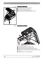
Page 104: ...tion box cover 1 Open the connection box cover A with a screwdriver 2 Pull off the connection box cover toward the front 3 Loosen the 3 screws C and remove the cover B Removing the rear covers from th...

Page 105: ...est fixed version 1 Loosen the screws A 2 Move the brackets B 3 Remove the footrest C Removing the Vario footrest 1 Lift the foot rest A at the foot end until the positioning joints C come away from t...

Page 106: ...over Service Manual Sinius Sinius CS Sinius TS 7 1 1 3 Removing the head and seat cushions Removing the head cushion Remove the upholstery on the headrest Removing the seat upholstery 1 Press the cush...

Page 107: ...ructions Removing the Lounge seat upholstery 1 Press the latching nose A inwards and tilt the seat upholstery upwards 2 Press the 2 latching noses C on both sides of the seat upholstery The cushion is...

Page 108: ...hion with motorized headrest Pull the cushion frame downward and out of the locking mechanism then lift and remove the cushion Velcro strip Slide the headrest cushion upward out of the locking mechani...

Page 109: ...D3561 076 01 07 02 02 2017 105 Dentsply Sirona 7 Replacing components Service Manual Sinius Sinius CS Sinius TS 7 1 Removing the cover b Motor driven headrest Release the latch A and remove the backr...

Page 110: ...e Manual Sinius Sinius CS Sinius TS 7 1 1 5 Removing the cover of the motorized headrest on the patient chair X 1 X 4 NSK V201 V215 V625 V209 V600 V212 V402 V303 V306 V307 V301 V523 V405 V502 V410 V52...

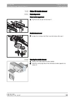
Page 111: ...he outer half shell covers A by twisting the screwdriver 2 Pull off the outer half shell covers 3 Open the inner half shell covers B by twisting the screwdriver 4 Loosen the inner half shell covers fr...

Page 112: ...ews 3 Press down on the 2 latching devices A 4 Fold back unit cover B and secure it with the prop C 7 1 2 3 Removing the user interface The dentist element is open 1 Unscrew the two screws A on the in...

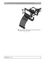
Page 113: ...1 3 Sinius CS dentist element 7 1 3 1 Removing covers Cover on the support arm Pry the cover A open and remove it Dentist element cover Loosen the 3 screws A of the cover and remove the cover 7 1 3 2...

Page 114: ...02 02 2017 7 Replacing components Dentsply Sirona 7 1 Removing the cover Service Manual Sinius Sinius CS Sinius TS 3 Unscrew the screws A and remove the washers 4 Lift the upper cover B at the front...

Page 115: ...07 02 02 2017 111 Dentsply Sirona 7 Replacing components Service Manual Sinius Sinius CS Sinius TS 7 1 Removing the cover b 5 Align the upper cover B with the front of the dentist element and guide it...

Page 116: ...emoving the cover Service Manual Sinius Sinius CS Sinius TS 7 1 4 Negatoscope 7 1 4 1 Removing the NAR board 1 Unscrew the two screws and remove the rear panel 2 Remove the fluorescent tubes 3 Unscrew...

Page 117: ...7 1 5 1 Removing the cover on the support arm 1 Use your fingers to grip the cover A from beneath and pull it off in a straight line 2 Spread the cover B open slightly with your fingers and lift the...

Page 118: ...lacken the two knurled screws A and remove the instrument holder B by pulling it forward 2 Unscrew the two mounting wedges and springs D and remove the two knurled screws A 3 Unscrew the three fasteni...

Page 119: ...and pull them away 2 Remove the service flap B 3 Unscrew the two screws from each of the covers C then unhook the covers and pull them away 4 Remove the lid D 5 Remove the four screws from the cover 6...

Page 120: ...7 Replacing components Dentsply Sirona 7 1 Removing the cover Service Manual Sinius Sinius CS Sinius TS 7 Remove the two screws from the lid G and lift it off 8 Remove the cover panel H of the funnel...

Page 121: ...Unscrew the screw and remove the DU cover D 5 Remove the LEDview E IMPORTANT Data backup Perform a treatment center data backup before replacing the lighting system with NLV or HLV board Check the gl...

Page 122: ...ply Sirona 7 1 Removing the cover Service Manual Sinius Sinius CS Sinius TS Removing LEDview angular support arm 1 Pry the cover A open and remove it 2 Unscrew the two screws from the lower cover pane...

Page 123: ...01 07 02 02 2017 119 Dentsply Sirona 7 Replacing components Service Manual Sinius Sinius CS Sinius TS 7 1 Removing the cover b 5 Unplug connectors X1 and X2 6 Remove the screw and pull off the bracket...

Page 124: ...ghting unit 1 Press the front cover together to release the snap lock and then remove the cover G 2 Unscrew the four screws G in the rear cover and remove the cover H 3 Unplug connectors X1 X5 and X6...

Page 125: ...ve the DU cover D 5 Remove the LEDview E IMPORTANT Data backup Perform a treatment center data backup before replacing the lighting system with NLV or HLV board Check the global software version of th...

Page 126: ...ius TS 6 Press the front cover together to release the snap lock and then remove the cover F 7 Unscrew the four screws G in the rear cover and remove the cover H 8 Unplug connector X1 from the HLV boa...

Page 127: ...7 02 02 2017 123 Dentsply Sirona 7 Replacing components Service Manual Sinius Sinius CS Sinius TS 7 1 Removing the cover b 7 1 8 LEDview Plus The removal of the covers is described in the LEDview Plus...

Page 128: ...dentist element Removing the NaCl pump If an NaCl pump is installed it must be removed before replacing the NAC HAC board 1 Release the screw A and open the PCB holder plate 2 Loosen the two screws B...

Page 129: ...vel arm of the dentist element b Removing boards 1 Pull connector X31 off of the NAJm board and the NAA board if present 2 Pull connectors X6 and X7 off of the NAA board if present 3 Remove the NAJm b...

Page 130: ...ards from the swivel arm of the dentist element Service Manual Sinius Sinius CS Sinius TS 7 If the NAC HAC board A with heat sinks is installed loosen the 6 metal screws and remove the board If the NA...

Page 131: ...it Before replacing boards Use the DUMC application to perform a data backup before replacing the following boards NAJm HSA NWEm NHE NHEm HAP2 HAP1 NLV XLV Tip DUMC Dental Unit Management Console see...

Page 132: ...treatment center OFF at the power switch before replacing a board Positio n Designation Value A Board ID HSA B Revision level 10 C Serial number of the board 4 D Software version after production Boot...

Page 133: ...on how to do this see Referencing the drives 35 2 Check the date and time in the Setup dialog box 7 3 4 NSK board in the patient chair The reference of the headrest is stored in the NSK board You have...

Page 134: ...these into the new board 2 Establish the same jumper setting of S1 as on the old board 7 3 6 NWEm board in the water unit Tip Cover the ventilation slots above the power supply when changing this boa...

Page 135: ...CS Sinius TS 7 3 Important information when replacing boards b 7 3 7 NAR board in the X ray viewer IMPORTANT While replacing the NAR board reconnect the lines from the old to the new board directly so...

Page 136: ...a 7 3 Important information when replacing boards Service Manual Sinius Sinius CS Sinius TS 7 3 8 HAC NAC board in the Sinius CS dentist element HAC NAC IMPORTANT If the NaCl pump is fitted it should...

Page 137: ...atment center on The pressure in the water unit is released 3 Activate the 3 way syringe SPRAYVIT E The water pressure is reduced Tip Activate the 3 way syringe SPRAYVIT E several times if necessary N...

Page 138: ...onnected 1 Dentist element user interface Hold down the Setup fixed key 2s The setup dialogs are displayed 2 Hold down the Service area fixed key 2s The service area will appear 3 Touch the arrow key...

Page 139: ...p fixed key on the user interface of the dentist element for at least 2 seconds Six setup dialogs are offered for selection 2 Touch the Service area key for at least 2 seconds The service area will ap...

Page 140: ...atic modules Service Manual Sinius Sinius CS Sinius TS 7 4 4 Solenoid valves for active lumbar support A55 A55 A56 MVKP2 MVKP1 A55 L238 L447 A55 A56 A56 A56 X14 Components Solenoid valves MVKP1 Lumbar...

Page 141: ...tion on how to do this see Referencing the drives 35 7 6 Solenoid value for Orotol Plus dosing CDS60 The dosing function can be deactivated in the service menu IMPORTANT For detailed information on re...

Page 142: ...63 69 149 D3561 138 D3561 076 01 07 02 02 2017 7 Replacing components Dentsply Sirona 7 6 Solenoid value for Orotol Plus dosing CDS60 Service Manual Sinius Sinius CS Sinius TS...

Page 143: ...d test and acoustic signals on the user interface You can switch the corresponding function LEDs on and off by pressing this key on the keyboard When you press Clean and Setup the 4 cursor LEDs are al...

Page 144: ...the service area Service Manual Sinius Sinius CS Sinius TS Approach packaging position Display service info service code lists Display and reset the maintenance interval Display treatment center infor...

Page 145: ...t key The function is available if there is an orange border surrounding the option HAP2 HAP1 Hardware bootloader and software version of the HAP2 HAP1 board HAPC Bootloader and operating system versi...

Page 146: ...8 Service area Dentsply Sirona 8 2 Information on the treatment center Service Manual Sinius Sinius CS Sinius TS NaCl pump Jumper on NAJm X24 4 5 Ultrasound Standard function ENDO Dongle on NAJm J11 N...

Page 147: ...nt Press the Assistant Element key The function is available if there is an orange border surrounding the option NHE Hardware bootloader and software version for the NHE board SRAYVIT Internal NHE com...

Page 148: ...is an orange border surrounding the option HSA Hardware bootloader and software version for the NSA board NSK Hardware and software version of the NSK board NSB Hardware and software version of the NS...

Page 149: ...stem 3kOhm characteristic resistance on NWEm X2 4 5 Motor detection on the board X ray viewer bridge on NAJ X15 A1 B1 Examination light check whether LED View NLV PCB available query via CAN If not th...

Page 150: ...Manual Sinius Sinius CS Sinius TS Is switched on in the subprogram to the chair program Forced chemical rinsing MV51 NWEm X35 B2 A2 present current measurement CDS60 detection Bridge X35 A1 B1 Air wa...

Page 151: ...e codes 1 Hold down the Setup fixed key 2s Six setup dialogs are offered for selection 2 To open one touch the Service Area key 2s The service area will appear 3 Touch the error log key The service co...

Page 152: ...date button 2 s The service interval is reset 8 5 Service support with the PC The Sirona Dental Unit Management Console Sirona DUMC application is available for service support This application offer...

Page 153: ...tion of the treatment center with the PC via the Ethernet interface and the practice network The function codes generated by specific operations in the treatment center are assigned to the desired PC...

Page 154: ...63 69 149 D3561 149 D3561 076 01 07 02 02 2017 8 Service area Dentsply Sirona 8 6 PC connection networking Service Manual Sinius Sinius CS Sinius TS...

Page 155: ...nd dentist element 9 1 1 Setting brakes on the Sinius support arm 1 Pull off the covers 2 Press the rubber cover down 3 Adjust the setscrew until the designed braking effect has been reached 9 1 2 Set...

Page 156: ...force if this is required Adjusting the brakes of the support arm 1 Pry the cover A open and remove it 2 Adjust the braking torque of the rear B and front C pivot bearings by tightening or loosening...

Page 157: ...brake force if this is required Adjusting the brakes of the support arm 1 Pull the cover A off from both sides 2 Adjust the braking torque of the rear B and front C pivot bearings by tightening or loo...

Page 158: ...ke force Using an Allen key turn the screw I inwards Reducing brake force Using an Allen key turn the screw I outwards Adjusting other joint brakes Adjusting the brake on the support arm 1 Increasing...

Page 159: ...position A Using an Allen key turn the screw H outwards 9 1 5 2 Adjusting the pneumatic spring on the support arm An Allen key with wrench width 8 is required for adjustment 1 Remove the protective ca...

Page 160: ...ressure so that the brake does not impede its movement 1 Switch the treatment center off 2 Actuate the SPRAYVIT to deaerate the treatment center IMPORTANT Practice oriented adjustment of the spring fo...

Page 161: ...rews A of the cover and remove the cover 2 Remove the top cover B 3 Open the flex arm covers C towards the dentist element This makes the adjustment screw D accessible hexagon socket head screw 4 mm 4...

Page 162: ...ment 1 Pull the cover B off from both sides 2 Open the flex arm covers C towards the dentist element This makes the adjustment screw D accessible hexagon socket head screw 4 mm 3 Adjust the spring for...

Page 163: ...controls b 9 3 Removing the swivel tray holder from the TS dentist s controls 9 3 1 Aligning the tray holder horizontally 1 Screw the tray arm on the dentist element using the screw B and the bevel w...

Page 164: ...components Dentsply Sirona 9 3 Removing the swivel tray holder from the TS dentist s controls Service Manual Sinius Sinius CS Sinius TS 3 Tighten the screw B firmly 9 3 2 Setting the brake on the tra...

Page 165: ...anical components Service Manual Sinius Sinius CS Sinius TS 9 3 Removing the swivel tray holder from the TS dentist s controls b 2 Turn the adjusting screw D in the direction to increase the brake for...

Page 166: ...9 4 Setting the Bowden wire in the motorized headrest Removing the covers 1 Unscrew the screw A and remove the upper cover B 2 Unscrew the 4 screws C and remove the lower cover D 3 Remove the cover o...

Page 167: ...d the Bowden wire B tight using pliers 2 Turn the tripping lever C until it covers the hole above the adjustment aid D 3 Pull the Bowden wire B out until the compression spring E is lightly pretension...

Page 168: ...63 69 149 D3561 162 D3561 076 01 07 02 02 2017 9 Mechanical components Dentsply Sirona 9 4 Setting the Bowden wire in the motorized headrest Service Manual Sinius Sinius CS Sinius TS...

Page 169: ...t all of the hose couplings to their maximum water flow rate and check this at all instruments 2 Remove the turbines straight and contra angle handpieces not the ultrasound handpiece 3 Remove the cove...

Page 170: ...off 9 Reduce the air pressure in the treatment center by operating the air button 10 Remove the filter and the sealing washer from AF1 A 11 Remove the filter and the sealing washer from AF6 B if this...

Page 171: ...n open end wrench SW19 If required have a container ready to catch any water that may run out 15 Connect the biofilm removal device pump to the sanitary hose 16 Connect a hose with valve on the extern...

Page 172: ...of the hose Switching the water flow on and off supports the process for removing deposits Close the valve again 6 Let cleaning solution 1 take effect in accordance with the instructions from the manu...

Page 173: ...opening the valve until water flows out of the hose Close the valve again 6 Let cleaning solution 2 take effect in accordance with the instructions from the manufacturer of the cleaning agent 7 Comple...

Page 174: ...treatment center by removing the Sprayvit and operating the water button until no more water emerges 2 Switch the treatment center off 3 Reduce the air pressure in the treatment center by operating th...

Page 175: ...it 7 Rinse all instrument hoses carrying water for approx 30 seconds by activating multiple times 8 Activate the tumbler filler 1x 9 Activate the flushing 1x 10 Activate the suction hose cleaning 1x...

Page 176: ...water 2 Check the tumbler filler and the flushing 3 Check the suction hose cleaning if present 4 Check the external device connection if present 5 Check all water channels for leaks filter cover corne...

Page 177: ...ovements Sirona Dental Systems GmbH Sprache englisch Printed in Germany D3561 076 01 07 02 02 2017 Nr 123 221 Sirona Dental Systems GmbH Contact in the USA Fabrikstra e 31 64625 Bensheim Germany Siron...

Page 178: ...63 69 149 D3561 171 D3561 076 01 07 02 02 2017 10 Biofilm removal Dentsply Sirona 10 4 Re processing Service Manual Sinius Sinius CS Sinius TS...

Reviews: