background image

Program - Individual Continuous Rotary Program

54/60

BENXSPSDFUWEB / Rev.09 / 10-2018

APPENDIX
Electromagnetic Emissions and Immunity (English) See 

page 55

.

13

PROGRAM - INDIVIDUAL CONTINUOUS 

ROTARY PROGRAM

For your individual settings of torque and speed values, please write file 
sizes and the corresponding values in the following table (for details see 
chapter 

6.7.3

):

Program default settings:

To restore default parameters, see chapter 

6.8 Factory Default 

Parameters

.

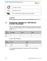
For indoor use only

Alternating current

This product meets UL safety standard requirements

File 
Position

File type

Ncm

Rpm

01
02

File 
Position

Ncm

Rpm

01

2.0

250

02

4.0

250

Summary of Contents for X-Smart Plus

Page 1: ...EN User Manual...

Page 2: ...2 60 BENXSPSDFUWEB Rev 09 10 2018 PAGE INTENTIONALLY LEFT BLANK...

Page 3: ...cting the Motor Handpiece 21 6 5 3 Connecting and Disconnecting the Contra angle 21 6 5 4 Inserting and Removing the File 22 6 5 5 Charging the Battery 22 6 5 6 Calibration 24 6 5 7 Sound Volume Adjus...

Page 4: ...Cleaning Disinfection and Sterilization 40 6 12 1 Foreword 40 6 12 2 General recommendations 40 6 12 3 Step by Step Procedure 41 7 Technical Specifications 43 7 1 Classifications of equipment 43 7 2 P...

Page 5: ...60 FOR DENTAL USE ONLY Introduction Congratulations on your purchase of the X Smart Plus endo motor Read this User Manual carefully before use for operating instructions care and maintenance Keep thi...

Page 6: ...rical equipment and has been cautioned against the use of small electrical appliances such as electric shavers hair dryers etc it is recommended not to use the X Smart Plus The use of X Smart Plus is...

Page 7: ...g period of time remove the battery to avoid fluid leak Do not expose the device to direct or indirect sources of heat Operate and store the device in a safe environment When installing the device lea...

Page 8: ...and cables sold by the manufacturer of the X Smart Plus as replacement parts for internal components may result in increased emissions or decreased immunity of the X Smart Plus X Smart Plus should no...

Page 9: ...not use files designed for reciprocating motion in continuous rotation Torque and speed values are subject to change by the file manufacturers without notice Therefore the preset values in the library...

Page 10: ...inal parts Should any anomalies arise during operation suspend work and contact your distributor Clinical judgment needs to be applied by the end user of the device 4 PRECAUTIONS Read these safety pre...

Page 11: ...n the device is powered on again Recharge rechargeable battery after it depletes as much as possible Repeating short time use and subsequent recharging may shorten its operating time due to the memory...

Page 12: ...6 STEP BY STEP INSTRUCTIONS Refer to the WARNINGS chapter see chapter 3 to verify any special care to exercise before starting to use the complete device Before use please check the exact contents of...

Page 13: ...with the components listed below 1 2 3 4 6 5 1 Control unit 2 Motor handpiece with cable and connector 3 X Smart Plus 6 1 contra angle 4 Handpiece stand 5 F type spray nozzle used for lubrication 6 AC...

Page 14: ...4 7 6 5 3 11 2 1 POWER Switches the device on and off keep pressed for more than 2 seconds 2 SPEED Adjust the rotation speed possible only for continuous rotary systems 3 TORQUE Adjust the torque limi...

Page 15: ...Automatic stop and reverse motion followed by stop when the preset torque is reached AUTO REVERSE OFF Auto reverse mode is not activated 10 CAL Calibrates the contra angle to ensure torque accuracy e...

Page 16: ...FILE Displays the selected file s See chapter 6 6 1 File Library 3 SPEED Displays the instrument rotation speed value disabled for reciprocating systems 4 TORQUE Displays the torque limit value disabl...

Page 17: ...ocating systems 3 modes can be selected see chapter 6 6 4 Auto Reverse Function AUTO REVERSING AUTO STOP AUTO REVERSE OFF No mark 7 ROTATIONAL DIRECTION Displays the current rotational direction of th...

Page 18: ...everse function may not activate See chapter 6 6 4 Auto Reverse Function Battery is drained or very low battery voltage Charge the battery see chapter 6 5 5 Charging the Battery NOTE The remaining amo...

Page 19: ...ir packaging and place them on a flat surface 2 Check that all the components listed in the STANDARD COMPONENTS chapter see chapter 6 1 are present 3 Remove the protective plastic film from the operat...

Page 20: ...see Fig 3 Fig 4 Power and Motor handpiece connectors A B 2 Charge the battery before the first use see chapter 6 5 5 Charging the Battery A Connect the AC adapter to the mains B Securely insert the co...

Page 21: ...ection 6 5 3 Connecting and Disconnecting the Contra angle Connecting The contra angle can be connected at 6 adjustable head positions Align the positioning pins of the contra angle with the positioni...

Page 22: ...ON When attaching and detaching the file turn the power off beforehand After the file is locked in place lightly pull out the file to make sure the file is locked Always clean the shank of the file to...

Page 23: ...e changes rapidly for example near to a window exposed to sunlight near the outlet of an air conditioner or heater the battery cannot be properly charged Store and charge this product in a place with...

Page 24: ...ion as the running properties can change with usage cleaning and sterilization The motor handpiece begins to rotate leave it as it is until it stops When the calibration process is completed the rotat...

Page 25: ...ion process turn the power off Calibrate every time the contra angle is lubricated or replaced after sterilizing or at least once a week see chapters 6 11 2 Lubricating the Contra angle and 6 12 Clean...

Page 26: ...t to update the file library and the systems contained in it WARNING Follow the file manufacturer s instructions for use of endodontic files The file system shown on the display must always match the...

Page 27: ...e POWER key for more than 2 seconds A welcome screen is displayed Then the display will read the first file in the system last used before switching the device off Switch off Hold down the POWER key f...

Page 28: ...e motor handpiece starts If you re press the key it stops If you hold down the ON OFF button for more than 1 second the motor handpiece starts while the key is pressed If you release the key it stops...

Page 29: ...iece will automatically rotate in the reverse direction When the load is removed the motor handpiece stops The LCD panel shows and the rotation speed alternately If you want the file to rotate forward...

Page 30: ...7 Selecting a File System To choose a different file system press the SYSTEM or key The file system shown in the display is the selected system NOTE This function is only available in continuous rotat...

Page 31: ...WaveOne Gold WaveOne RECIPROC and RECIPROC blue files are designed specifically for use in reciprocation whereby the instrument is driven first in a cutting direction and then reverses to release the...

Page 32: ...tinguished from continuous rotary files by their special design the spiral is inverted and the shaft is equipped with a colored plastic ring In reciprocating motion the auto reverse function is disabl...

Page 33: ...r To individually change these settings simply overwrite them as described below This allows you to compile your own instrument sequence independently from file manufacturer or recommended sequences T...

Page 34: ...ue value is changed from the default setting TORQUE is displayed between brackets If the MEMO key is not pressed to save the setting the setting will be lost once a different file setting is selected...

Page 35: ...l Metal Hydride batteries can experience a decrease in charging capacity if repeated cycles of short time use and recharging are carried out This phenomenon is called the memory effect The battery ref...

Page 36: ...r more than 2 seconds if you want to stop this process NOTE This function is not activated unless the device is powered by the AC adapter This function is not required for each charging This function...

Page 37: ...otation power weaker and the battery refresh function has not resolved the problem When replacing be sure to observe the following PRECAUTIONS ON CHANGING BATTERY Note that Dentsply Sirona shall not b...

Page 38: ...removing the battery cord make sure to hold it at the connector Failure to do so may damage the cord 6 Insert the battery cord connector into the device connector in accordance with the polarity indi...

Page 39: ...he rear part of the contra angle and lubricate for 2 3 seconds until oil comes out from the contra angle head 3 Before attaching the lubricated contra angle to the motor handpiece wipe off excess oil...

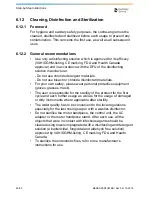
Page 40: ...your own safety please wear personal protective equipment gloves glasses mask The user is responsible for the sterility of the product for the first cycle and each further usage as well as for the us...

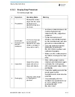
Page 41: ...d observe concentrations given by the manufacturer see also general recommendations Use only approved washer disinfector according to EN ISO 15883 maintain and calibrate it regularly Make sure the con...

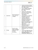
Page 42: ...manufacturer Use only this recommended sterilization procedure Control the efficiency packaging integrity no humidity color change of sterilization indicators physico chemical integrators digital reco...

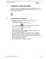
Page 43: ...rotection against electric shock Class II equipment and internally powered equipment Degree of protection against electric shock Type B applied part Degree of protection against ingress of water as de...

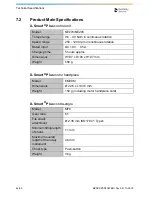
Page 44: ...ion Speed range 250 1200 rpm in continuous rotation Rated input DC 18 V 0 5 A Charging time 5 hours approx Dimensions W107 x D196 x H107 mm Weight 580 g Model EM09M Dimensions 22 6 x L133 5 mm Weight...

Page 45: ...AND STORING CONDITIONS Model TR30RAM180 CINCON ELECTRONICS CO LTD Input AC 100 240 V 47 63 Hz Output DC 18 V 1 67 A Dimensions W62 x D37 x H109 mm Weight 300 g Temperature 10 C 40 C 50 F 104 F Humidit...

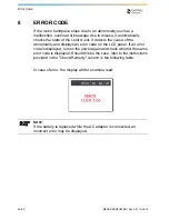
Page 46: ...cause of the abnormality and displays an error code on the LCD panel If an error code is displayed turn on the power again and check whether the same error code is displayed Should this be the case re...

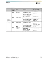
Page 47: ...rrent The motor handpiece is locked at the time of the auto reverse mode Remove load The motor handpiece cord has shorted Contact your distributor E 02 Over voltage Malfunction of circuit Contact your...

Page 48: ...generated in start stop circuit Faulty start stop circuit from PAM L Slide Contact your distributor E 06 Rotor lock The motor handpiece is locked at the time of startup Remove load Faulty contra angl...

Page 49: ...malfunction Contact your distributor E 14 Beyond the range of working temperature Beyond the range of working temperature or damage to the thermistor in the battery section Use within the range of wo...

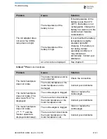
Page 50: ...there is no electricity in the outlet Check the connection The battery is flat Charge the battery or use the AC adapter No battery is inserted Insert battery or use the AC adapter The internal fuse ha...

Page 51: ...layed See chapter 8 X Smart Plus motor handpiece Problem Cause Solution The motor handpiece does not rotate The motor handpiece cord is not connected Check the connection The motor handpiece or the mo...

Page 52: ...ower is turned on while pressing the ON OFF key Check the ON OFF key There is a short circuit inside the ON OFF key Contact your distributor The motor handpiece keeps rotating The motor handpiece is r...

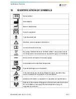
Page 53: ...st absolutely be recycled through your distributor Direct current connection for power supply Autoclavable at the specified temperature Opened packages are not replaced If the instructions are not bei...

Page 54: ...l settings of torque and speed values please write file sizes and the corresponding values in the following table for details see chapter 6 7 3 Program default settings To restore default parameters s...

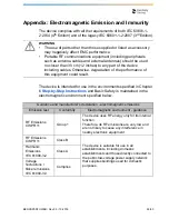
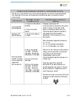
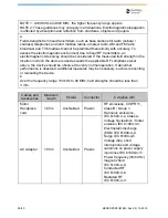
Page 55: ...ed no closer than 30 cm 12 inches to any part of the device including cables Otherwise degradation of the performance of this equipment could result Guidance and manufacturer s declaration electromagn...

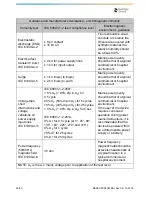
Page 56: ...nt Voltage dips short interruptions and voltage variations on power supply input lines IEC 61000 4 11 IEC 60601 1 2 2007 5 UT 95 dip in UT for 0 5 cycle 40 UT 60 dip in UT for 5 cycles 70 UT 30 dip in...

Page 57: ...requency of the transmitter Recommended separation distance d 1 2 P d 1 2 P 80 MHz to 800 MHz d 2 3 P 800 MHz to 2 5 GHz Where P is the maximum output power rating of the transmitter in watts W accord...

Page 58: ...vice is used exceeds the applicable RF compliance level above the device should be observed to verity normal operation If abnormal performance is observed additional measures may be necessary such as...

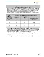
Page 59: ...W Separation distance according to frequency of transmitter m 150 kHz to 80 MHz d 1 2 P 80 MHz to 800 MHz d 1 2 P 800 MHz to 2 5 GHz d 2 3 P 0 01 0 12 0 12 0 23 0 1 0 38 0 38 0 73 1 1 2 1 2 2 3 10 3...

Page 60: ...BENXSPSDFUWEB Rev 09 10 2018 dentsplysirona com Maillefer Instruments Holding S rl Chemin du Verger 3 CH 1338 Ballaigues Switzerland email endo dentsplysirona com 0086...

Reviews: