background image

FISDR-JAP / F1902124.X / 02 / 2011 – updated 07/2012 

- 102 / 209 -


6.5.6. 

Kalibrierung


Diese  Funktion  dient  zur  Reduzierung  der  Schwankungen  in  der  Drehzahl  des 
Motorhandstücks  und  zum  Ausgleich  von  Drehmoment-Unterschieden  im  Vergleich  zum 
Winkelstück. 
Eine  Kalibrierung  ist  empfehlenswert,  wenn  neue  oder  andere  Winkelstücke  zum  Einsatz 
kommen  oder  das  Gerät  über  einen  langen  Zeitraum  betrieben  wurde,  da  sich  die 
Laufeigenschaften bei Betrieb, Reinigung und Sterilisation verändern können. 
 
1.


Das Gerät ausschalten

2.


Das X-SMART Plus 6:1 Winkelstück am Motorhandstück befestigen. 

3.


Den AC-Adapter anschließen und darauf achten, dass die AC-IN-Lampe leuchtet. 

4.


Das Gerät einschalten

5.


Die CAL (10) Taste (siehe Abb. 1) länger als 2 Sekunden gedrückt halten. 


Während der Kalibrierung wird auf dem Display Folgendes angezeigt:  


Das  Motorhandstück  beginnt  zu  rotieren.  Die  Rotation  bis  zum  Ende  ungestört  ablaufen 
lassen. 


Nach  der  Kalibrierung  ist  die  Rotation  beendet.  Auf  dem  Display  wird  nun  Folgendes 
angezeigt: 


Anschließend kehrt das Display zur ursprünglichen Anzeige zurück. 
 

Summary of Contents for Xsmart plus

Page 1: ...FISDR JAP F1902124 X 02 2011 updated 07 2012 0 209 USER MANUAL ...

Page 2: ...FISDR JAP F1902124 X 02 2011 updated 07 2012 1 209 ...

Page 3: ...kvireres på følgende sprog Portugisisk POR Hollandsk NL Dansk DK Svensk S Finsk FIN græsk GR Polsk POL Lettiske LV Estiske EE og Litauiske LT Ελληνική Αυτή η οδηγία είναι επίσης διαθέσιµη κατόπιν ζήτησης στις ακόλουθες γλώσσες Πορτογαλέζικη POR Oλλaνδική NL ανέζικη DK Σουηδική S Φιλανδέζικη FIN Ελληνική GR Πολωνική POL Λετονίας LV Εσθονίας EE και Λιθουανίας LT Polski Ta instrukcja obsługi jest rów...

Page 4: ...FISDR JAP F1902124 X 02 2011 updated 07 2012 3 209 ...

Page 5: ...ttery 21 6 5 6 Calibration 22 6 5 7 Sound Volume Adjustment 23 6 6 Operation 23 6 6 1 File Library 23 6 6 2 Switch on and Switch off the Unit 24 6 6 3 Switch on and Switch off the Motor Handpiece 24 6 6 4 Auto Reverse Function 25 6 7 Selecting a File System 26 6 7 1 Continuous Rotary File Systems 26 6 7 2 Reciprocating File Systems 27 6 7 3 Program for Continuous Rotary File Systems 28 6 7 4 Chang...

Page 6: ...1 Classifications of Equipment 35 7 2 Product Main Specifications 35 8 Error Code 37 9 Troubleshooting 40 10 Warranty 41 11 Disposal of the Product 42 12 Identification of Symbols 42 13 Program Individual Continuous Rotary Program 43 APPENDIX Electromagnetic Emissions and Immunity 206 ...

Page 7: ...07 2012 6 209 FOR DENTAL USE ONLY Introduction Congratulations on your purchase of the X SMART Plus endo motor Read this User Manual carefully before use for operating instructions care and maintenance Keep this manual for future reference ...

Page 8: ...se WARNINGS The device must only be used in suitable locations and only by specialized physicians licensed to practice dentistry Use the specified battery for this device Never use any other batteries than those that Dentsply Maillefer specifies Use the Dentsply Maillefer AC adapter for this device Never use any other AC adapters If you should notice battery fluid leak deformation of the motor han...

Page 9: ... replacement parts for internal components may result in increased emissions or decreased immunity of the X SMART Plus The X SMART Plus should not be used adjacent to or stacked with other equipment In the instance that if adjacent or stacked use is necessary the X SMART Plus should be observed to verify normal operation in the configuration in which it will be used None of the X SMART Plus compon...

Page 10: ...ve force is applied If the motor handpiece overheats too often or overheating persists contact your distributor Before starting the motor handpiece verify the correctness of the motor settings The AC adapter must be supplied at a voltage ranging between 100 240 V 10 47 63 Hz Use only original parts Should any anomalies arise during operation suspend work and contact your distributor Clinical judgm...

Page 11: ...are recyclable but their disposal may sometimes not be permitted by law in your location Return them to your distributor When disposing of the control unit follow the instructions of your local government for disposal as they contain materials which may become industrial waste When discarding the contra angle and motor handpiece dispose of them as medical waste This product does not consider a pat...

Page 12: ... Ambient Conditions for Operation Use indoor Ambient temperature 10 C 40 C 50 F 104 F Relative humidity 30 75 Atmospheric pressure 700hPa 1060hPa The original packing materials may be stored and shipped in ambient conditions of 10 C to 50 C from 14 F to 122 F with relative humidity at 10 85 and atmospheric pressure at 500hPa to 1060hPa WARNING Do not install the device in damp places or in places ...

Page 13: ...h the components listed below 1 Control unit 2 Motor handpiece with cable and connector 3 X SMART Plus 6 1 contra angle 4 Handpiece stand 5 F type spray nozzle used for lubrication 6 AC adapter model Cincon Electronics Co Ltd TR30RAM180 with EU UK USA AUS exchangeable plugs Torque card User Manual 5 1 2 4 3 6 ...

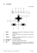
Page 14: ...peed possible only for continuous rotary systems 3 TORQUE Adjust the torque limit possible only for continuous rotary systems 4 5 SYSTEM Change the file system 6 7 FILE Change the file within a system 8 REV Changes the rotational direction of the file only possible for continuous rotary systems The rotational direction can also be changed while the file is in motion 1 10 9 8 12 6 4 7 13 14 2 11 3 ...

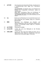
Page 15: ... not activated 10 CAL Calibrates the contra angle to ensure torque accuracy each time the contra angle is replaced or lubricated keep pressed for more than 2 seconds 11 MEMO Saves modifications to the speed torque limit values and auto reverse mode in each system where modifications are possible keep pressed for more than 2 seconds 12 SOUND VOLUME Adjusts the sound volume 13 AC IN LAMP Lights gree...

Page 16: ...for reciprocating systems 4 TORQUE Displays the torque limit value disabled for reciprocating systems 5 TORQUE BAR Displays the bar graph which shows the degree of load applied to the motor while the file is in continuous rotation disabled for reciprocating systems 6 AUTO REVERSE Displays the selected auto reverse mode disabled for reciprocating systems 3 modes can be selected see chapter 6 6 4 Au...

Page 17: ...ng the Battery Full charge Approximately 30 80 remains Less than 30 remains In this case the auto reverse function may not activate See chapter 6 6 4 Auto reverse function Battery is drained or very low battery voltage Charge the battery see chapter 6 5 5 Charging the Battery NOTE The remaining amount of battery mark indicates a voltage When a load is applied to the motor handpiece the remaining a...

Page 18: ...e operation panel WARNING Should any liquid exit the device interrupt the installation immediately and send the machine to your distributor 6 5 Installation 6 5 1 Connecting the AC adapter 1 Select the plug adapter that matches your electric power outlet for the power supply Fig 3 Plug adapters for power supply Place the required plug adapter onto the two contacts on the power supply and push it t...

Page 19: ... 4 on the left side of the device c Completely charge the battery prior to first use CAUTION To disconnect the cables always hold at the central part of the connector and pull out Do not pull the cable 6 5 2 Connecting and Disconnecting the Motor Handpiece Connecting Align the mark of the cord plug with the mark of the unit connector B see Fig 4 at the left side of the device and insert the plug u...

Page 20: ...er off beforehand Check that the contra angle is securely assembled to the motor handpiece 6 5 4 Inserting and Removing the File File insertion Insert the file into the chuck until it stops Lightly turn the file until it engages with the latch mechanism Push inwards to click File removal Press the push button and pull out the file see Fig 6 Fig 6 CAUTIONS When attaching and detaching the file turn...

Page 21: ... condition of the battery temperature and whether the battery is new or old Older batteries may remarkably shorten both the charging and operating time When charging the temperature of the battery is measured Therefore if this product is placed in an environment where the temperature changes rapidly for example near to a window exposed to sunlight near the outlet of an air conditioner or heater th...

Page 22: ...wer on 5 Hold down the CAL 10 key see Fig 1 for more than 2 seconds During the calibration process the display will read The motor handpiece begins to rotate leave it as it is until it stops When the calibration process is completed the rotation stops and the display reads Then the display returns to its original state NOTES Should you at any time wish to stop the calibration process turn the powe...

Page 23: ...library with the following preset NiTi systems A Continuous rotary systems Gates PathFile Protaper Universal Protaper Next Program individual programs B Reciprocating systems WaveOne RECIPROC The manufacturer reserves the right to update the file library and the systems contained in it WARNINGS Follow the file manufacturer s instructions for use of endodontic files The file system shown on the dis...

Page 24: ...ds NOTE If 10 minutes pass without operation the power turns off automatically auto power off function 6 6 3 Switch on and Switch off the Motor handpiece If you press the ON OFF key briefly the motor handpiece starts If you re press the key it stops If you hold down the ON OFF button for more than 1 second the motor handpiece starts while the key is pressed If you release the key it stops NOTE If ...

Page 25: ...se direction When the load is removed the motor handpiece stops The LCD panel shows and the rotation speed alternately If you want the file to rotate forward again press the ON OFF key twice Load within the Torque Limit Value Further Loading beyond the preset Torque Limit Value If the load is kept applied the file will rotate in reverse When the load is removed Stop Reverse Rotation Forward Rotati...

Page 26: ...the remaining amount of battery indicates If a load is continuously applied to the motor handpiece it may automatically stop to prevent overheating In this case leave the motor handpiece for a while until it cools down 6 7 Selecting a File System To choose a different file system press the SYSTEM or key The file system shown in the display is the selected system 6 7 1 Continuous Rotary File System...

Page 27: ...ht part of the display WARNING Do not use files designed for continuous rotation in reciprocating motion NOTES For reciprocating files the settings including speed and torque cannot be adjusted Reciprocating files can be distinguished from continuous rotary files by their special design the spiral is inverted and the shaft is equipped with a colored plastic ring In reciprocating motion the auto re...

Page 28: ...ary Program 6 7 4 Changing Speed and Torque NOTES Speed and torque cannot be changed for reciprocating systems While the motor handpiece is in motion speed and torque can be changed but they cannot be saved When the desired continuous rotary file is selected press the or SPEED keys to select the desired speed setting When the speed value is changed from the default setting SPEED is displayed betwe...

Page 29: ...ameters follow the general reset instructions 1 Turn the power off 2 Connect the AC adapter and check that the AC IN lamp lights see chapter 6 5 1 Connecting AC adapter 3 Hold down the POWER key for more than 2 seconds while pressing the MEMO key During the process the display will read When the process is completed the display reads Then the display returns to the first system of the file library...

Page 30: ... 6 Hold down the POWER key for more than 2 seconds if you want to stop this process NOTES This function is not activated unless the device is powered by the AC adapter This function is not required for each charging This function should be used if the operating time is shortened even if the battery is relatively new Do not repeat the battery refresh function in a short period of time It may result...

Page 31: ... leakage or explode Do not change the battery with wet hands as this may cause short circuiting of the battery and moisture infiltrating the device The battery compartment is located at the rear of the unit and its cover is secured by a screw located on the bottom of the unit 1 Turn the power off 2 Disconnect the AC adapter 3 Remove the screw fixing the cover with a screw driver 4 Slide the cover ...

Page 32: ...nd before sterilization 1 Screw the spray nozzle onto the spray with approx 10 turns 2 Insert the spray nozzle into the rear part of the contra angle and lubricate for 2 3 seconds until oil comes out from the contra angle head 3 Before attaching the lubricated contra angle to the motor handpiece wipe off excess oil Place it on its end or lean it at an angle for gravity draining Mount it after exce...

Page 33: ...ur own safety please wear personal protective equipment gloves glasses mask The user is responsible for the sterility of the product for the first cycle and each further usage as well as for the usage of damaged or dirty instruments where applicable after sterility The water quality has to be convenient to the local regulations especially for the last rinsing step or with a washer disinfector Do n...

Page 34: ...an adequate spray before packaging 4 Packaging Pack the contra angle in Sterilization pouches Check the validity period of the pouch given by the manufacturer to determine the shelf life Use packaging which is resistant to a temperature up to 141 C 286 F and in accordance with EN ISO 11607 5 Sterilization Steam sterilization at 134 C 274 F for 3 minutes Use only autoclaves that are matching the re...

Page 35: ... protection against ingress of water as detailed in the current edition of IEC 60529 IPX0 Degree of safety of application in the presence of a flammable anesthetic mixture with air or with oxygen or nitrous oxide Not suitable for use in the presence of a flammable anesthetic mixture with air or oxygen or nitrous dioxide Mode of operation Continuous operation 7 2 Product Main Specifications X SMART...

Page 36: ...hank 11 mm Maximum overall length of the rotary instrument 46 mm Chuck type Push button Weight 36 g X SMART Plus AC adapter Model TR30RAM180 CINCON ELECTRONICS CO LTD Input AC 100 240 V 47 63 Hz Output DC 18 V 1 67 A Dimensions W62 x D37 x H109 mm Weight 300 g ENVIRONMENTAL CONDITIONS FOR USE Temperature 10 C 40 C 50 F 104 F Humidity 30 75 Atmospheric pressure 700hPa 1060hPa TRANSPORT AND STORING ...

Page 37: ...the cause of the abnormality and displays an error code on the LCD panel If an error code is displayed turn on the power again and check whether the same error code is displayed Should this be the case refer to the instructions provided in the Check Remedy column in the following table In case of error the display will for example read NOTE If the battery is replaced while the AC adapter is connec...

Page 38: ...tor E 06 Rotor lock The motor handpiece is locked at the time of startup Remove load Faulty contra angle Motor faulty Faulty sensor Hall IC Severed cord Signal Power line Contact your distributor E 08 Over current Shorted cord power line Shortstop of the motor winding Contact your distributor E 09 ITRIP Faulty motor and circuit Contact your distributor At the time of charging E 10 Battery current ...

Page 39: ...the battery If abnormal heat generates from the new battery as well malfunction of the circuit may be suspected Contact your distributor E 16 LCD panel Faulty LCD Contact your distributor At the time of calibration E 18 Beyond the upper limit The operating life of the motor handpiece or contra angle has expired Replace the motor handpiece or contra angle E 19 Below the lower limit ...

Page 40: ...IN lamp does not light The AC adapter is not connected Check the connection The plug of the AC adapter is not inserted into the outlet or there is no electricity in the outlet Check the connection The internal fuse has burnt Contact your distributor The AC adapter fuse has burnt Contact your distributor The AC adapter does not work The CHRG lamp does not light No battery is inserted Insert battery...

Page 41: ... pressing the ON OFF key Check the ON OFF key There is a short circuit inside the ON OFF key Contact your distributor The motor handpiece keeps rotating The motor handpiece is rotated by the ON OFF key Stop the rotation by the ON OFF key Continuous rotary file blocks in the root canal Wrong file setting Too much pressure on the instrument Change the rotational direction by pressing the REV key Sta...

Page 42: ...y be recycled through your distributor Direct current connection for power supply Autoclavable at the specified temperature Opened packages are not replaced WARNING If the instructions are not being followed properly operation may result in hazards for the product or the user patient NOTE Additional information explanation on operation and performance Marking on the outside of Equipment or Equipme...

Page 43: ... please write file sizes and the corresponding values in the following table for details see chapter 6 7 3 File Position File type Ncm Rpm 01 02 03 04 05 06 07 Program default settings File Position Ncm Rpm 01 1 0 250 02 1 5 250 03 2 0 250 04 2 5 250 05 3 0 250 06 3 5 250 07 4 0 250 To restore default parameters see chapter 6 8 Factory Default Parameters ...

Page 44: ...sation 62 6 6 1 Bibliothèque de limes 62 6 6 2 Mise sous tension et hors tension de l unité 63 6 6 3 Mise sous tension et hors tension de la pièce à main 64 6 6 4 Fonction d inversion automatique Auto reverse 64 6 7 Sélection d un système de lime 66 6 7 1 Systèmes de lime à rotation continue 66 6 7 2 Systèmes de lime à rotation alternée 66 6 7 3 Program pour les systèmes de lime à rotation continu...

Page 45: ...de l équipement 76 7 2 Caractéristiques principales du produit 76 8 Codes d erreurs 78 9 Résolution de problèmes 81 10 Garantie 82 11 Élimination du produit 83 12 Identification des symboles 83 13 Program Programme personnalisé pour rotation continue 84 APPENDIX Electromagnetic Emissions and Immunity 206 ...

Page 46: ...roduction Félicitations pour l achat de votre moteur d endodontie X SMART Plus Lire attentivement ce manuel avant utilisation pour connaître les instructions relatives au fonctionnement à l entretien et à la maintenance de l appareil Conserver ce manuel pour vous y référer ultérieurement ...

Page 47: ...ient Lire attentivement les mises en garde ci dessous avant utilisation MISES EN GARDE Le dispositif ne peut être utilisé que dans des endroits appropriés et par des praticiens spécialisés habilités à exercer l art dentaire N utiliser que la batterie indiquée pour ce produit Ne jamais utiliser d autres batteries que celles recommandées par Dentsply Maillefer Utiliser exclusivement l adaptateur AC ...

Page 48: ...duits inflammables Utiliser et conserver le dispositif dans un environnement sûr Il se peut que le système présente un mauvais fonctionnement lorsque celui ci est soumis à l interférence d un champ électromagnétique Ne pas installer X SMART Plus à proximité d un appareil émettant des ondes magnétiques L utilisation d accessoires capteurs et câbles autres que ceux indiqués à l exception des capteur...

Page 49: ...ue lorsque le contre angle X SMART Plus d origine est utilisé correctement entretenu et lubrifié pour plus de précisions se reporter au chapitre 6 11 2 Lubrification du contre angle Ne pas utiliser de contre angle ou réducteur autre que celui d origine Ne jamais insérer de lime dans le contre angle pendant la calibration Répéter la calibration à chaque fois que le contre angle est lubrifié ou remp...

Page 50: ...e son installation Forcer sa mise en place dans la mauvaise direction peut endommager le système et causer une fuite de liquide de batterie suite à un court circuit Les batteries rechargeables pleinement chargées se déchargent généralement au bout d un certain temps même si le système n a pas servi depuis quelque temps Il est donc recommandé de recharger la batterie juste avant utilisation Si le d...

Page 51: ...dontie X SMART Plus ne peut être stérilisé à l exception du contre angle 5 Effets indésirables Il n existe aucun effet indésirable connu 6 Instructions détaillées Se reporter au chapitre Mises en garde voir chapitre 3 pour connaître les précautions spécifiques à mettre en œuvre avant de commencer à utiliser l ensemble du dispositif Avant utilisation vérifier le contenu de l emballage Conditions d ...

Page 52: ... Pièce à main micromoteur avec câble et connecteur 3 X SMART Plus 6 1 contre angle 4 Support de pièce à main 5 Embout pour pulvérisation de Type F utilisé pour la lubrification 6 Adaptateur AC modèle TR30RAM180 de Cincon Electronics Co Ltd avec connecteurs interchangeables pour l Europe le Royaume Uni les Etats Unis et l Australie Carte des couples Manuel d utilisation 5 1 4 3 6 2 ...

Page 53: ...t pour les systèmes à rotation continue 3 TORQUE Permet de régler la valeur limite de couple disponible uniquement pour les systèmes à rotation continue 4 5 SYSTEM Permet de changer de système de lime 6 7 FILE Permet de changer de lime dans un système 8 REV Permet de changer le sens de rotation de la lime disponible uniquement pour les systèmes à rotation continue Le sens de rotation peut égalemen...

Page 54: ...e 10 CAL Permet de calibrer le contre angle pour garantir la précision du couple à chaque remplacement ou lubrification du contre angle maintenir appuyé pendant plus de 2 secondes 11 MEMO Permet d enregistrer les modifications de vitesse valeur limite de couple et mode auto reverse dans chaque système où celles ci sont possibles maintenir appuyé pendant plus de 2 secondes 12 VOLUME Permet de régle...

Page 55: ...aleur limite de couple désactivé pour les systèmes à rotation alternée 5 NIVEAU DE COUPLE Affiche la barre de progression indiquant le niveau de charge appliquée au moteur lorsque la lime fonctionne en rotation continue désactivé pour les systèmes à rotation alternée 6 AUTO REVERSE Affiche le mode auto reverse sélectionné désactivé pour les systèmes à rotation alternée 3 modes peuvent être sélecti...

Page 56: ...la batterie Pleine charge Environ 30 à 80 Reste moins de 30 Dans ce cas la fonction auto reverse peut ne pas s activer voir chapitre 6 6 4 Fonction d inversion automatique La batterie est vide ou très faible Charger la batterie voir chapitre 6 5 5 Recharger la batterie NOTE Le symbole de niveau de batterie restant indique une tension Lorsqu une charge est appliquée à la pièce à main du moteur le n...

Page 57: ... commande MISE EN GARDE En cas de fuite de liquide interrompre immédiatement l installation et renvoyer le dispositif à votre distributeur 6 5 Installation 6 5 1 Alimentation électrique 1 Sélectionner l adaptateur d alimentation correspondant aux prises secteur locales FIG 3 Adaptateurs pour prises électriques Placer l adaptateur choisi sur les deux contacts du bloc d alimentation et le pousser ve...

Page 58: ... du dispositif c Charger complètement la batterie avant la première utilisation MISE EN GARDE Pour débrancher les câbles toujours saisir la partie centrale du connecteur et tirer Ne pas tirer le câble 6 5 2 Connecter et déconnecter la pièce à main Connecter Aligner le symbole de la fiche du cordon de la pièce à main avec le symbole du connecteur du moteur B voir Fig 4 à la gauche de l unité et ins...

Page 59: ...e du contre angle procéder en suivant l axe Fig 5 FIG 5 MISES EN GARDE Mettre le produit hors tension avant l insertion ou le retrait du contre angle Vérifier que le contre angle est attaché de manière sûre à la pièce à main 6 5 4 Insertion et retrait de la lime Insertion de la lime Insérer l instrument dans le mandrin jusqu à la butée Tourner légèrement l instrument jusqu à ce qu il s engage dans...

Page 60: ...dispositif sous tension pour charger la batterie La diode AC IN s allume pour indiquer que l appareil est sous tension Elle ne s éteint pas après la charge complète de la batterie Voir la diode CHRG afin de vérifier l état de charge de la batterie Le temps de charge standard est de 5 heures environ mais peut varier selon les conditions d utilisation de la batterie la température et l âge de la bat...

Page 61: ...angle Il est recommandé d effectuer une calibration lorsqu un nouveau autre contre angle est utilisé ou après une période prolongée d utilisation car les caractéristiques de fonctionnement peuvent varier après plusieurs utilisations nettoyages et stérilisations 1 Mettre le produit hors tension 2 Fixer le contre angle 6 1 X SMART Plus à la pièce à main 3 Connecter l adaptateur AC et s assurer que l...

Page 62: ...ux différents fort faible et muet le son est au niveau faible lors des confirmations et erreurs mais il est inactif pendant la rotation inverse ou lorsque la valeur limite de couple est atteinte 1 Appuyer sur la touche du volume 12 voir Fig 1 2 Le volume et le symbole sur l écran LCD changent REMARQUES Le dernier volume utilisé est conservé en mémoire même si le dispositif est mis hors tension Si ...

Page 63: ...itesse sans avis préalable Il convient donc de vérifier les valeurs prédéfinies dans la bibliothèque avant utilisation Les valeurs de couple indiquées à l écran ne sont précises et fiables que lorsque des contre angles X SMART Plus 6 1 correctement entretenus et lubrifiés sont utilisés 6 6 2 Mise sous tension et hors tension de l unité Mise sous tension Maintenir la touche POWER appuyée pendant pl...

Page 64: ...e la vitesse de rotation et de la valeur limite de couple utilisez respectivement les touches SPEED et TORQUE 6 6 4 Fonction d inversion automatique Auto reverse Trois modes auto reverse différents sont disponibles AUTO REVERSE Si en cours d utilisation la charge atteint la valeur limite de couple préprogrammée la pièce à main change automatiquement de sens de rotation Quand la charge diminue la p...

Page 65: ...alerte sonore est émise l écran affiche Le son émis change lorsque la charge approche de la valeur limite de couple l écran affiche REMARQUES Cette fonction est disponible uniquement en rotation continue Cette fonction n est pas activée en rotation inverse Quand l indication de la capacité restante de la batterie montre la pression réelle appliquée peut ne pas atteindre la valeur limite de couple ...

Page 66: ...lectionner la lime précédente MISES EN GARDE Ne pas utiliser de limes à rotation alternée en mode continu 6 7 2 Systèmes de lime à rotation alternée Les limes WaveOne et RECIPROC sont spécialement conçues pour être utilisées en mode réciprocité un mouvement selon lequel l instrument est dirigé dans un sens de coupe puis est relâché en tournant dans la direction opposée Les angles de réciprocité so...

Page 67: ...le maximum est atteint le moteur s arrête Dans ce cas retirer la lime du canal radiculaire nettoyer les spires et redémarrer le moteur 6 7 3 Program pour les systèmes de lime à rotation continue Par souci de commodité le dispositif est livré avec 7 programmes avec des valeurs de couple et de vitesse par défaut voir chapitre 13 Appuyer sur la touche FILE pour sélectionner le numéro de programme sui...

Page 68: ...i sur la touche MEMO il sera perdu lors de la sélection d une autre lime La valeur de vitesse peut être réglée de 250 à 1000 tr min par incréments de 50 tr min et de 1000 à 1200 tr min par incréments de 100 tr min Appuyer sur les touches TORQUE ou pour sélectionner la valeur de couple souhaitée Lorsque la valeur de couple d origine est modifiée TORQUE est affiché entre crochets Si le paramétrage n...

Page 69: ...électrique 3 Maintenir la touche POWER appuyée pendant plus de 2 secondes tout en appuyant sur la touche MEMO Pendant le processus l écran affiche le message suivant Une fois le processus terminé l écran affiche Puis l écran revient au premier système de la bibliothèque de limes REMARQUES Cette fonction n est pas activée si le dispositif n est pas branché sur le secteur Il convient de noter que to...

Page 70: ...ER appuyée pendant plus de 2 secondes pour l interrompre REMARQUES Cette fonction n est pas activée si le dispositif n est pas branché sur le secteur Cette opération n est pas nécessaire à chaque charge Elle doit être effectuée si l autonomie de la batterie diminue même si celle ci est relativement neuve Ne pas répéter l opération de régénération de la batterie de manière rapprochée dans le temps ...

Page 71: ...rence A1007 000 00 100 Tout autre type de batteries pourrait endommager le produit causer une fuite ou exploser Ne pas changer la batterie avec les mains mouillées Ceci pourrait causer un mauvais fonctionnement dû à un court circuit de la batterie et une infiltration d humidité dans l appareil Le compartiment de la batterie se trouve à l arrière de l unité et son couvercle est fixé par une vis sit...

Page 72: ...Lubrifier après chaque utilisation et avant stérilisation 1 Visser approximativement 10 tours l embout sur la bombe lubrifiante 2 Insérer l embout dans la partie arrière du contre angle et lubrifier pendant 2 à 3 secondes jusqu à ce que l huile sorte de la tête du contre angle 3 Avant de fixer le contre angle lubrifié à la pièce à main essuyer l excès d huile Placer le contre angle verticalement o...

Page 73: ...porter les équipements de protection individuelle requis gants lunettes masque L utilisateur est responsable de la stérilisation du produit pour le premier cycle et chaque utilisation suivante aussi bien que pour l utilisation d instruments endommagés ou sales après la stérilisation La qualité de l eau devra être conforme à la règlementation locale en vigueur et tout particulièrement concernant l ...

Page 74: ...s par le fabricant voir aussi Recommandations générales Le laveur désinfecteur devra obligatoirement être conforme à la norme EN ISO 15883 et faire l objet d un entretien et d un étalonnage réguliers Assurez vous que le contre angle soit sec avant de continuer à l étape suivante 3 Inspection Contrôler l état du contre angle et se débarrasser de ceux qui présentent un défaut Si le contre angle est ...

Page 75: ...s protocoles de stérilisation que celui indiqué Vérifier que l efficacité obtenue est correcte intégrité de l emballage aucune humidité changement de couleur des indicateurs de stérilisation intégrateurs physico chimiques enregistrements numériques des paramètres de cycles Garantir la traçabilité des protocoles enregistrés 6 Stockage Placer le sachet de stérilisation contenant le contre angle dans...

Page 76: ...contre l ingérence d eau tel que détaillé dans l édition courante de la norme CEI 60529 IPX0 Niveau de sécurité pour une utilisation en présence d un mélange anesthésique inflammable avec l air l oxygène ou l oxyde d azote non adapté à une utilisation en présence d un mélange anesthésique inflammable avec l air l oxygène ou l oxyde d azote Mode de fonctionnement Fonctionnement continu 7 2 Caractér...

Page 77: ... 11 mm Longueur maximale hors tout de l instrument rotatif 46 mm Type de mandrin Bouton poussoir Poids 36 g Adaptateur AC X SMART Plus Modèle TR30RAM180 CINCON ELECTRONICS CO LTD Entrée AC 100 240 V 47 63 Hz Sortie DC 18 V 1 67 A Dimensions 62 x 37 x 109 mm Poids 300 g CONDITIONS ENVIRONNEMENTALES D UTILISATION Température 10 C 40 C 50 F 104 F Humidité 30 75 Pression atmosphérique 700hPa 1060hPa C...

Page 78: ...ifié La cause du problème est détectée et un code erreur est affiché sur l écran LCD Remettre le produit sous tension et vérifier que le même code d erreur réapparaît Si tel est le cas faire le nécessaire selon les instructions fournies sous la colonne Check Remède dans le tableau suivant En cas d erreur l écran affiche par exemple REMARQUE Si la batterie est remplacée alors que l adaptateur AC es...

Page 79: ...ffet Hall Cordon coupé ligne de signaux Contacter votre distributeur E 04 Surchauffe du moteur Une forte pression a été appliquée en continu à la pièce à main sur une période relativement longue Laisser le moteur refroidir avant de reprendre l utilisation E 05 Circuit MIA Tension anormale générée dans le circuit de commutation Circuit de commutation du MIA défaillant L Slide Contacter votre distri...

Page 80: ...ension de la batterie est trop élevée dysfonctionnement du circuit Contacter votre distributeur E 14 Température prescrite dépassée Température prescrite dépassée ou capteur de température endommagée dans la partie batterie Travailler dans la plage de température donnée ou remplacer la batterie Autre E 15 Dégagement de chaleur anormal au niveau de la batterie La batterie dégage une chaleur anormal...

Page 81: ...otre distributeur La diode AC IN ne s allume pas L adaptateur AC n est pas connecté Vérifier la connexion La fiche de l adaptateur AC n a pas été insérée dans la prise de courant ou cette prise n est pas alimentée en courant Vérifier la connexion Le fusible interne a fondu Contacter votre distributeur Le fusible interne à l adaptateur AC a fondu Contacter votre distributeur Le chargeur de batterie...

Page 82: ...ouche ON OFF Il y a un court circuit à l intérieur de la touche ON OFF Contacter votre distributeur La rotation de la pièce à main continue La pièce à main est actionnée à l aide de la touche ON OFF Stopper la rotation avec la touche ON OFF La lime à rotation continue se bloque dans le canal radiculaire Mauvaise configuration de lime Pression excessive sur l instrument Changer le sens de rotation ...

Page 83: ...ivent être recycles par l intermédiaire de votre distributeur Courant continu Autoclavable Emballage ouvert non remplacé WARNING Le non respect des instructions peut entraîner des risques pour le produit ou l utilisateur patient NOTE Informations complémentaires ou explications relatives à l utilisation et aux performances du produit Marquage à l extérieur d un appareil ou de pièces d un appareil ...

Page 84: ... personnalisées de couple et de vitesse pour plus de précisions voir chapitre 6 7 3 Position de la lime Type de lime N cm tr min 01 02 03 04 05 06 07 Paramètres par défaut Position de la lime N cm tr min 01 1 0 250 02 1 5 250 03 2 0 250 04 2 5 250 05 3 0 250 06 3 5 250 07 4 0 250 Pour rétablir les paramètres par défaut se reporter au chapitre 6 8 Paramètres par défaut définis en usine ...

Page 85: ...FISDR JAP F1902124 X 02 2011 updated 07 2012 84 209 ...

Page 86: ...der Lautstärke 104 6 6 Betrieb 104 6 6 1 Feilen Bibliothek 104 6 6 2 Einschalten und Ausschalten des Geräts 105 6 6 3 Einschalten und Ausschalten des Motorhandstücks 105 6 6 4 Auto Reverse Funktion 106 6 7 Wahl des Feilensystems 107 6 7 1 Feilensysteme mit kontinuierlicher Rotation 108 6 7 2 Feilensysteme mit reziproker Rotation 108 6 7 3 Program für Systeme mit kontinuierlicher Rotation 109 6 7 4...

Page 87: ...ierung des Geräts 117 7 2 Technische Daten 118 8 Fehlercode 119 9 Behebung von Störungen 122 10 Garantiehinweise 123 11 Entsorgung des Produkts 124 12 Standardsymbole 124 13 Program Individuelle Programme für kontinuierliche Rotation 125 APPENDIX Electromagnetic Emissions and Immunity 206 ...

Page 88: ...AHNÄRZTLICHEN GEBRAUCH Einführung Herzlichen Glückwunsch zum Kauf des X SMART Plus Endo Motors Bitte die folgenden Angaben zu Bedienung Pflege und Wartung vor der Inbetriebnahme des Geräts sorgfältig durchlesen Die Gebrauchsanleitung zu Nachschlagezwecken aufbewahren ...

Page 89: ...che Gefahrenquellen für das Gerät bzw den Anwender Patienten Bitte vor der Inbetriebnahme die folgenden Warnhinweise durchlesen WARNHINWEISE Dieses Gerät darf nur in geeigneten Räumlichkeiten und nur von approbierten Zahnärzten verwendet werden Stets den für dieses Produkt vorgesehenen Akku verwenden Niemals andere Akkus verwenden als von Dentsply Maillefer angegeben Dieses Produkt nur in Verbindu...

Page 90: ...onen des Geräts liegen unterhalb der Grenzwerte die in den diesbezüglich geltenden Vorschriften EN 60601 1 2 2007 festgelegt sind Das Gerät keinesfalls in Gegenwart von freiem Sauerstoff Anästhetika oder anderen entzündlichen Substanzen betreiben Elektromagnetische Wellen können zu Funktionsstörungen des Gerätes führen X SMART Plus nicht in der Nähe eines Geräts installieren das elektromagnetische...

Page 91: ...ur bei sachgerecht gepflegten und geschmierten X SMART Plus 6 1 Winkelstücken korrekt und verlässlich Ein korrekter Antrieb durch den Mikromotor ist nur bei Gebrauch sachgerechter Pflege und Schmierung des X SMART Plus 6 1 Origninal Winkelstücks gewährleistet weitere Details siehe 6 11 2 Schmieren des Winkelstücks Nur das Original Winkelstück und das angegebene Untersetzungsverhältnis verwenden Wä...

Page 92: ... Einsetzen des Akkus auf die korrekte Ausrichtung des Anschlusses achten Ein gewaltsames Einsetzen in falscher Richtung kann eine Beschädigung und das Austreten von Flüssigkeit aufgrund eines Kurzschlusses zur Folge haben Voll aufgeladene Akkus entladen sich im Laufe der Zeit selbst wenn das Gerät nicht in Gebrauch ist Es wird empfohlen den Akku erst kurz vor der Verwendung wieder aufzuladen Wenn ...

Page 93: ...t sterilisierbar außer das Winkelstück 5 Unerwünschte Wirkungen Es sind keine unerwünschten Wirkungen bekannt 6 Anwendung Schritt für Schritt Vor dem Gebrauch des Geräts und des Zubehörs unter WARNHINWEISE siehe Kapitel 3 nachlesen welche besonderen Vorkehrungen zu treffen sind Vor der Inbetriebnahme bitte die Lieferung auf Vollständigkeit überprüfen Umgebungsbedingungen beim Betrieb des Geräts Ve...

Page 94: ...ors umfasst folgende Teile 1 Bediengerät 2 Motorhandstück mit Kabel und Stecker 3 X SMART Plus 6 1 Winkelstück 4 Handstück Ständer 5 Sprühdüse Typ F zum Schmieren 6 AC Adapter Modell Cincon Electronics Co Ltd TR30RAM180 mit austauschbaren Steckern für EU UK USA AUS Drehmoment Karte Gebrauchsanleitung 1 2 3 6 4 5 ...

Page 95: ...ei Systemen mit kontinuierlicher Rotation 3 TORQUE Anpassung der Drehmomentbegrenzung nur bei Systemen mit kontinuierlicher Rotation 4 5 SYSTEM Wechsel des Feilensystems 6 7 FILE Feilenwechsel innerhalb desselben Systems 8 REV Änderung der Drehrichtung der Feile nur bei Systemen mit kontinuierlicher Rotation Die Drehrichtung kann auch bei Rotation der Feile geändert werden 1 10 9 8 12 6 5 4 7 13 1...

Page 96: ...rse Modus ist nicht aktiviert 10 CAL Kalibrierung des Winkelstücks für ein korrektes Drehmoment nach jedem Auswechseln oder Schmieren länger als 2 Sekunden gedrückt halten 11 MEMO Speicherung von Änderungen der Drehzahl und Drehmomentgrenzwerte sowie des Auto Reverse Modus bei allen Systemen die Änderungen zulassen länger als 2 Sekunden gedrückt halten 12 LAUTSTÄRKE Einstellung der Lautstärke 13 A...

Page 97: ...er Rotation 4 TORQUE Anzeige des Drehmomentgrenzwertes deaktiviert für Systeme mit reziproker Rotation 5 TORQUE BAR Anzeige des Belastungsgrades des Motors durch die dargestellte Balkengrafik bei kontinuierlicher Rotation der Feile deaktiviert für Systeme mit reziproker Rotation 6 AUTO REVERSE Anzeige des gewählten Auto Reverse Modus deaktiviert für Systeme mit reziproker Rotation Es können 3 Modi...

Page 98: ...azität ca 30 bis 80 Verbleibende Kapazität weniger als 30 In diesem Zustand kann die Auto Reverse Funktion eventuell nicht aktiviert werden siehe Kapitel 6 6 4 Auto Reverse Funktion Der Akku ist leer oder die Akkuspannung ist sehr niedrig Den Akku aufladen siehe Kapitel 6 5 5 Laden des Akkus HINWEIS Das Symbol für die verbleibende Akkuleistung zeigt einen Spannungswert an Wenn das Motorhandstück b...

Page 99: ...nen WARNHINWEIS Falls aus dem Gerät eine Flüssigkeit austreten sollte die Installation sofort abbrechen und das Gerät an den Händler zurückschicken 6 5 Installation 6 5 1 Anschluss des AC Adapters 1 Den für Ihre Steckdose geeigneten Adapter für das Netzteil auswählen Abb 3 Adapter für das Netzteil Den ausgewählten Adapter auf die beiden Kontakte am Netzteil legen und in Richtung Arretierknopf B sc...

Page 100: ...s Geräts einschieben c Den Akku vor dem Erstgebrauch voll aufladen ACHTUNG Um die Verbindung zu trennen stets den Stecker in der Mitte festhalten und herausziehen Nicht am Kabel ziehen 6 5 2 Anschließen und Trennen des Motorhandstücks Anschließen Das Symbol des Kabelsteckers auf das Symbol des Geräteanschlusses B siehe Abb 4 auf der linken Seite des Geräts ausrichten und den Stecker einführen bis ...

Page 101: ...Zum Entfernen des Winkelstücks Winkelstück gerade herausziehen siehe Abb 5 Abb 5 ACHTUNG Vor dem Anbringen und Abnehmen des Winkelstücks Stromzufuhr abschalten Darauf achten dass der Winkelstückkopf sicher am Motorhandstück befestigt ist 6 5 4 Einsetzen und Entfernen der Feile Einsetzen der Feile Die Feile bis zum Anschlag in das Spannfutter schieben Die Feile leicht drehen bis sie in den Schnappm...

Page 102: ...lle des Ladevorgangs auf die CHARGE Lampe achten Die Aufladezeit beträgt normalerweise ca 5 Stunden kann aber je nach Verwendung Zustand Temperatur und Alter des Akkus variieren Insbesondere bei alten Akkus kann sowohl die Aufladezeit als auch die Betriebsdauer deutlich kürzer sein Beim Aufladen wird die Akkutemperatur gemessen Wird das Gerät in einer Umgebung aufgestellt in der schnelle Temperatu...

Page 103: ...etrieb Reinigung und Sterilisation verändern können 1 Das Gerät ausschalten 2 Das X SMART Plus 6 1 Winkelstück am Motorhandstück befestigen 3 Den AC Adapter anschließen und darauf achten dass die AC IN Lampe leuchtet 4 Das Gerät einschalten 5 Die CAL 10 Taste siehe Abb 1 länger als 2 Sekunden gedrückt halten Während der Kalibrierung wird auf dem Display Folgendes angezeigt Das Motorhandstück begin...

Page 104: ...ertönen mit niedriger Lautstärke bei einer Bestätigung oder einem Fehler jedoch nicht bei Linksdrehung oder Erreichen des Drehmomentgrenzwerts 1 Die Lautstärke Taste 12 drücken siehe Abb 1 2 Die Lautstärke und das Lautstärke Symbol auf dem LCD Display ändern sich HINWEISE Die zuletzt eingestellte Lautstärke wird beibehalten auch wenn das Gerät ausgeschaltet wird Beim Zurücksetzen auf die Voreinste...

Page 105: ...X SMART Plus 6 1 Winkelstücken korrekt und verlässlich 6 6 2 Einschalten und Ausschalten des Geräts Einschalten Die Taste EIN AUS länger als 2 Sekunden gedrückt halten Es wird eine Begrüßung angezeigt Anschließend wird die erste Feile des letzten vor dem Ausschalten des Geräts verwendeten Systems angezeigt Ausschalten Die Taste EIN AUS länger als 2 Sekunden gedrückt halten HINWEIS Wird das System ...

Page 106: ...automatisch zur normalen Vorwärtsdrehung zurück AUTO STOP Wenn die Last während des Betriebs den voreingestellten Drehmomentgrenzwert erreicht rotiert das Motorhandstück automatisch in die Gegenrichtung Wird die Last entfernt stoppt das Motorhandstück Das LCD Display zeigt abwechselnd und die Drehzahl an Wenn die Feile wieder nach rechts rotieren soll zweimal die EIN AUS Taste drücken ON OF Taste ...

Page 107: ...ur bei kontinuierlicher Rotation verfügbar Diese Funktion ist bei Rotation in Gegenrichtung nicht aktiviert Wenn für die verbleibende Akkuleistung das Symbol angezeigt wird reicht die aktuelle Leistung des Motorhandstücks möglicherweise nicht aus um den voreingestellten Drehmomentgrenzwert zu erreichen In diesem Fall wird die Auto Reverse Funktion nicht aktiviert Sollte ein hohes Drehmoment erford...

Page 108: ... Rotation WaveOne und RECIPROC Instrumente wurden speziell für die Verwendung im reziproken Modus entwickelt in dem das Instrument zuerst in Schneiderichtung angetrieben und dann durch Umkehr der Drehrichtung wieder freigegeben wird Die Drehwinkel der reziproken Bewegung sind präzise und speziell auf die Form des Instruments und den X SMART Plus Endo Motor ausgerichtet Wenn eine der oben genannten...

Page 109: ...maximalen Drehmoments stoppt der Motor In diesem Fall die Feile aus dem Wurzelkanal nehmen die Nuten reinigen und neu starten 6 7 3 Program für Systeme mit kontinuierlicher Rotation Das Gerät bietet 7 praktische Programme mit Drehmoment und Drehzahl Standardwerten siehe Kapitel 13 Program Individuelle Programme für kontinuierliche Rotation Die Taste FILE drücken um die nächste Programmnummer auszu...

Page 110: ...schten Drehmomenteinstellung die Tasten oder TORQUE drücken Wenn ein anderer Drehmomentwert als die Voreinstellung verwendet wird wird in Klammern TORQUE angezeigt Wenn die Taste MEMO Taste nicht gedrückt wird um die Einstellung zu speichern geht die Einstellung verloren sobald eine andere Feileneinstellung gewählt wird Das Drehmoment ist von 0 6 bis 4 0 Ncm in Schritten von 0 1 Ncm einstellbar Be...

Page 111: ...ach nur kurzer Anwendungsdauer erneut aufgeladen werden Dieses Phänomen wird allgemein als Memory Effekt bezeichnet Mit der Akku Refresh Funktion kann dieses Problem behoben werden 1 Das Gerät ausschalten 2 Den AC Adapter anschließen und darauf achten dass die AC IN Lampe leuchtet siehe Kapitel 6 5 1 Anschluss des AC Adapters 3 Die EIN AUS Taste länger als 2 Sekunden gedrückt halten und gleichzeit...

Page 112: ...und ein Feilensystem mit kontinuierlicher Rotation auswählen 2 Die Tasten und TORQUE gleichzeitig länger als 2 Sekunden gedrückt halten Auf dem Display wird die Software Version angezeigt zum Beispiel Danach wird auf dem Display wieder das erste System der Feilen Bibliothek angezeigt 6 11 Wartung 6 11 1 Auswechseln des Akkus X SMART Plus wird mit einem Akku betrieben der sich je nach den Betriebsb...

Page 113: ...unten schieben und abnehmen 5 Den Akku herausnehmen und das Kabel am Stecker anfassen und herausziehen ACHTUNG Vor dem Auswechseln des Akkus AC Adapter entfernen Das Akkukabel beim Herausziehen unbedingt am Stecker anfassen Andernfalls kann das Kabel beschädigt werden 6 Den Kabelstecker des Akkus entsprechend der Polaritätsangabe auf dem Etikett im Inneren des Akkufachs in die vorgesehene Buchse s...

Page 114: ...cks am Motorhandstück abwischen Das Winkelstück aufstellen oder so anlehnen dass das Öl ablaufen kann Erst befestigen wenn das überschüssige Öl abgelaufen ist WARNHINWEIS Nicht das Motorhandstück schmieren ACHTUNG Das Winkelstück gut festhalten damit es durch den Druck des Sprays nicht abgelöst wird Die Spraydose niemals verkehrt herum benutzen Ansonsten tritt nur Spraygas und kein Öl aus 6 12 Rei...

Page 115: ...m Erstgebrauch und bei der Wiederverwendung sowie für eine eventuelle Verwendung beschädigter oder noch verunreinigter Instrumente nach der Sterilisation Die Wasserqualität muss den örtlichen Vorschriften entsprechen Dies gilt insbesondere für die letzte Spülung bzw den Einsatz eines Reinigungs und Desinfektionsgeräts Motorhandstück Bediengerät AC Adapter und Handstück Ständer nicht sterilisieren ...

Page 116: ...he auch Allgemeine Hinweise und Empfehlungen beachten Nur zertifizierte Reinigungs und Desinfektionsgeräte gemäß EN ISO 15883 verwenden Diese regelmäßig warten und kalibrieren Vor dem nächsen Schritt sicherstellen dass das Winkelstück trocken ist 3 Kontrolle Das Winkelstück überprüfen und defekte Teile aussortieren Schmutzige Winkelstücke müssen erneut gereinigt und desinfiziert werden Das Winkels...

Page 117: ...lität kann nicht garantiert werden wenn die Verpackung offen beschädigt oder nass ist Die Verpackung und das Winkelstück vor dem Gebrauch kontrollieren unbeschädigte Verpackung keine Feuchtigkeit Haltbarkeit 7 Technische Daten Das Gerät entspricht den Normen IEC 60601 1 zur Sicherheit und IEC60601 1 2 zur EMV elektromagnetischen Verträglichkeit und erfüllt die Anforderungen für die CE Kennzeichnun...

Page 118: ...580 g X SMART Plus Motorhandstück Modell EM09M Maße Ø 22 6 x L 133 5 mm Gewicht 150 g einschließlich Motorhandstück Kabel X SMART Plus Winkelstück Modell MF6 Untersetzungsverhältnis 6 1 Feilenschaft Ansatz Ø 2 35 mm ISO1797 1 Typ 1 Minimale Schafteinspannlänge 11 mm Maximale Länge des rotierenden Instrumentes 46 mm Spannfuttertyp Druckknopf Gewicht 36 g X SMART Plus AC Adapter Modell TR30RAM180 CI...

Page 119: ...lastung Bruch oder unsachgemäßer Verwendung wird automatisch der Zustand der Bedieneinheit geprüft Das Gerät erkennt die Fehlerursache und zeigt auf dem LCD Display einen Fehlercode an Wenn ein Fehlercode angezeigt wird das Gerät erneut einschalten und nachsehen ob derselbe Fehlercode wieder erscheint Sollte dies der Fall sein unter Prüfung Abhilfe in der folgenden Tabelle nachschlagen Bei einem F...

Page 120: ...ckierter Rotor Das Motorhandstück blockiert beim Starten Last entfernen Fehlerhaftes Winkelstück Fehlerhafter Motor Fehlerhafter Sensor Hall IC Durchtrenntes Kabel Signal Stromleitung Händler kontaktieren E 08 Überstrom Kurzschluss im Strom Kabel Kurzschluss in Motorwicklung Händler kontaktieren E 09 ITRIP Motor und Stromkreis fehlerhaft Händler kontaktieren Beim Aufladen E 10 Akkustrom Der Akkust...

Page 121: ...austauschen Wenn sich der neue Akku auch übermäßssig erhitzt ist vermutlich eine Störung im Stromkreis die Ursache Händler kontaktieren E 16 LCD Anzeige Fehlerhafte LCD Händler kontaktieren Bei der Kalibrierung E 18 Obergrenze überschritten Die Lebensdauer des Motorhandstücks oder des Winkelstücks ist überschritten Motorhandstück oder Winkelstück ersetzen E 19 Untergrenze unterschritten ...

Page 122: ...ebrannt Händler kontaktieren Die AC IN Lampe leuchtet nicht Der AC Adapter ist nicht angeschlossen Anschluss überprüfen Der Stecker des AC Adapters ist nicht an die Steckdose angeschlossen oder die Steckdose ist nicht mit dem Stromnetz verbunden Anschluss überprüfen Die interne Sicherung ist durchgebrannt Händler kontaktieren Die Sicherung des AC Adapters ist durchgebrannt Händler kontaktieren Der...

Page 123: ...prüfen Es besteht ein Kurzschluss im Inneren der EIN AUS Taste Händler kontaktieren Das Motorhandstück hält nicht an Die Rotation wurde mit der EIN AUS Taste gestartet Rotation mit der EIN AUS Taste stoppen Eine kontinuierlich rotierende Feile blockiert im Wurzelkanal Falsche Feileneinstellung Es wird zu viel Druck auf das Instrument ausgeübt Drehrichtung durch Betätigung der REV Taste ändern Den ...

Page 124: ...hstrom Anschluss für Netzteil Autoklavierbar bei der angegebenen Temperatur Geöffnete Verpackung nicht ersetzbar WARNING Durch ungenügende Beachtung dieser Warnhinweise kann der Betrieb des Geräts gefährlich für das Gerät bzw den Anwender Patienten sein NOTE Zusätzliche Hinweise bzw Erläuterungen zu Funktion und Leistung Kennzeichnung auf der Außenseite von Geräten oder Geräteteilen die HF Sender ...

Page 125: ... bitte Feilengröße und entsprechende Werte in die folgende Tabelle eintragen Details siehe Kapitel 6 7 3 Feilenposition Feilentyp Ncm Rpm U min 01 02 03 04 05 06 07 Voreinstellungen Feilenposition Ncm Rpm U min 01 1 0 250 02 1 5 250 03 2 0 250 04 2 5 250 05 3 0 250 06 3 5 250 07 4 0 250 Zur Wiederherstellung der Voreinstellungen siehe Kapitel 6 8 Werkseitige Voreinstellungen ...

Page 126: ...5 7 Ajuste de volumen del sonido 144 6 6 Funcionamiento 144 6 6 1 Biblioteca de Limas 144 6 6 2 Encendido y apagado la unidad 145 6 6 3 Encendido y apagado de la pieza de mano del motor 145 6 6 4 Función Auto Reverse 146 6 7 Selección de un Sistema de Limas 147 6 7 1 Sistema de Limas de Rotación Continua 147 6 7 2 Sistema de Limas de giro alterno 148 6 7 3 Program para Sistema de Limas de Rotación...

Page 127: ...l equipo 156 7 2 Principales especificaciones del producto 157 8 Código de errores 158 9 Persistencia del problema 161 10 Garantía 162 11 Retirada del producto 163 12 Identificación de símbolos 163 13 Program Programa Individual de Rotación Continua 164 APÉNDICE Emisiones electromagnéticas e inmunidad 206 ...

Page 128: ...AL Introducción Felicidades por adquirir el motor de endodoncia X SMART Plus Leer cuidadosamente este Manual del Usuario antes de usar el motor X SMART Plus para conocer las instrucciones de funcionamiento cuidado y mantenimiento Guardar este manual para futuras consultas ...

Page 129: ...descripción de las reacciones adversas serias y daños de seguridad potenciales para el producto para el paciente o el usuario Leer las siguientes advertencias antes de usarlo ADVERTENCIAS El aparato puede solo usarse en lugares apropiados y solo por dentistas Usar las baterías específicas para este producto Nunca usar otras baterías que no especifique Dentsply Maillefer Usar el adaptador CA de Den...

Page 130: ...ites recomendados según las regulaciones pertinentes EN 60601 1 2 2007 No usar el aparto en presencia de oxígeno libre sustancias anestésicas o productos inflamables Usar y guardar el aparato en ambiente seguro Es posible que el aparato funcione mal si se usa en presencia de alguna interferencia por onda electromagnética No colocar X SMART Plus cerca de aparatos que emitan ondas electromagnéticas ...

Page 131: ... contra ángulos X SMART Plus 6 1 perfectamente mantenidos y lubricados La exactitud del movimiento proporcionado por el motor solo se garantiza si se usa el contra ángulo X SMART Plus 6 1 perfectamente mantenido y lubricado para más detalles ver capitulo 6 11 2 Lubricación del contra ángulo No usar ningún otro contra ángulo ni otro valor de reducción que el recomendado No insertar ninguna lima en ...

Page 132: ...rección del conector de la batería cuando la instale Si se colocan mal puede causar daño y escape del líquido debido a un cortocircuito La pieza de mano consume electricidad aunque el aparato esté apagado Además las baterías recargables totalmente cargadas en general se van descargando con el tiempo aunque no se usen Se recomienda cargar las baterías justo antes de su uso Si el aparato se parara a...

Page 133: ... ángulo 5 Reacciones Adversas No existen reacciones adversas conocidas 6 Instrucciones Paso a Paso Referirse al capítulo de ADVERTENCIAS ver capítulo 3 para verificar cualquier cuidado especial a realizar antes de empezar a usar el aparato Antes de su uso por favor comprobar el contenido exacto del embalaje Condiciones Ambientales para el funcionamiento Uso interior Temperatura ambiente 10 C 40 C ...

Page 134: ...muestran abajo 1 Unidad central 2 La pieza de mano del motor con cable y conector 3 X SMART Plus 6 1 contra ángulo 4 Soporte de la pieza de mano 5 Boquilla tipo F de spray usada para lubricar 6 Cargador externo de batería modelo Cincon Electronics Co Ltd TR30RAM180 con EU UK USA AUS enchufes intercambiables Tarjeta de torque Manual del usuario 5 4 2 3 1 6 ...

Page 135: ...rotación solo para sistemas de rotación continua 3 TORQUE Ajusta el límite de torque solo para sistemas de rotación continua 4 5 SISTEMA Cambia el sistema de limas 6 7 LIMA Cambia la lima dentro de cada sistema 8 REV Cambia el sentido de rotación de la lima solo para los sistemas de rotación continua El sentido de rotación de la lima puede cambiarse también mientras la lima esta en movimiento 1 10...

Page 136: ...bra el contra ángulo para asegurar un torque exacto cada vez que el contra ángulo se quita o se lubrica mantener apretado durante mas de 2 segundos 11 MEMO Guarda las modificaciones de los valores de velocidad torque y modo de auto reverse en cada sistema cuando son posibles las modificaciones mantener apretado durante mas de 2 segundos 12 VOLUMEN DE SONIDO Ajusta el volumen del sonido 13 LUZ ENCE...

Page 137: ...giro alterno 4 TORQUE indica el valor límite de torque deshabilitado para los sistemas de giro alterno 5 BARRA DE TORQUE Muestra la barra que indica el grado de carga aplicada al motor mientras la lima esta en rotación continua deshabilitado para los sistemas de giro alterno 6 AUTO REVERSE Muestra el modo auto reverse seleccionado deshabilitado para los sistemas de giro alterno Se pueden seleccion...

Page 138: ...r capítulo 6 5 5 Carga de la batería Carga completa Queda un 30 80 aproximadamente Queda menos del 30 En este caso la función de auto reverse puede que no funcione ver capítulo 6 6 4 Función Auto reverse La batería está agotada o queda muy poca Cargar la batería ver capítulo 6 5 5 Carga de la batería NOTA La marca de reserva de batería indica el voltaje Cuando se plica una carga a la pieza de mano...

Page 139: ...a unidad ADVERTENCIA Si saliera algún líquido del aparato interrumpir la instalación inmediatamente y enviar la máquina a su distribuidor 6 5 Instalación 6 5 1 Conectar el cargador de batería 1 Seleccionar el adaptador de enchufe que se ajuste a la clavija de su proveedor según el país Fig 3 Adaptadores para el suministro eléctrico Colocar el adaptador de enchufe requerido en la zona donde están l...

Page 140: ...do izquierdo del aparato c Cargar completamente la batería antes del primer uso ADVERTENCIA Para desconectar los cables siempre sujetar de la parte central del enchufe y tirar No tirar del cable 6 5 2 Conectar y desconectar la pieza de mano del motor Conectar Alinear la marca del conector del cable con la marca del conector de la unidad B ver Fig 4 en el lado izquierdo de la unidad e insértelo has...

Page 141: ... hacia fuera sin inclinarlo ver Fig 5 Fig 5 PRECAUCIÓN Cuando quitemos o coloquemos el contra ángulo apagar la unidad previamente Comprobar que la cabeza del contra ángulo está perfectamente ajustada a la pieza de mano 6 5 4 Inserción y extracción de la lima Colocación de la lima Insertar el mandril de la lima hasta el fondo Girar la lima suavemente hasta que se enganche con el mecanismo de cierre...

Page 142: ...da Observar la luz de CARGA para comprobar las condiciones de la carga El tiempo normal de carga es de 5 horas aproximadamente pero variará en función de las condiciones de uso de las baterías temperatura y si las baterías son nuevas o usadas Las baterías usadas acortan considerablemente el tiempo de carga y el de uso Cuando se esté cargando las baterías se mide la temperatura de la batería Por ta...

Page 143: ...er la unidad 5 Apretar el botón CAL 10 Ver Fig 1 durante más de dos segundos Durante el proceso de calibración aparece en la pantalla La pieza de mano empieza a rotar dejarla hasta que se pare sola Cuando el proceso de calibración haya terminado se detiene el movimiento de rotación y aparece en la pantalla Luego la pantalla vuelve a su estado original NOTA SI se quisiera detener el proceso de cali...

Page 144: ... NiTi memorizados A Sistemas de rotación continua Gates PathFile Protaper Universal Protaper Next Program programas individuales B Sistemas de giro alterno WaveOne Reciproc El fabricante se reserva el derecho a actualizar la biblioteca de limas y los sistemas presentes ADVERTENCIAS Seguir las instrucciones de uso del fabricante para las limas endodóncicas El sistema de limas que se muestra en el d...

Page 145: ...10 minutos no se hace nada la unidad se apaga automáticamente función de apagad automático 6 6 3 Encendido y apagado de la pieza de mano del motor Si apretamos el botón ON OFF la pieza de mano empieza a funcionar Si volvemos a apretarlo se para Si mantenemos apretado el botón ON OFF durante más de un segundo la pieza de mano empieza a funcionar mientras el botón esté apretado Si se suelta el botón...

Page 146: ...e el botón ON OFF dos veces AUTO REVERSE OFF Auto reversa desactivado Si durante la utilización la fuerza alcanza el valor límite de torque preseleccionado la pieza de mano del motor se parará sin girar en sentido inverso La pantalla muestra y la velocidad de rotación de forma alterna Si se quiere que la lima vuelva a girar en sentido normal otra vez apretar dos veces el botón ON OFF Carga con el ...

Page 147: ... función de auto reverse no se activará Si se necesitara un torque alto usar el adaptador AC o utilizar el aparato cuando el símbolo de la cantidad de batería remanente indique Si la resistencia está presente de forma continua sobre la pieza de mano automáticamente se parará para prevenir sobrecalentamiento En este caso dejar que la pieza de mano se enfríe 6 7 Selección de un Sistema de Limas Para...

Page 148: ...la parte derecha de la pantalla ADVERTENCIA No usar limas diseñadas para rotación continua con movimiento de giro alterno NOTAS Para las limas de giro alterno los ajustes de velocidad y torque no se pueden ajustar Las limas de giro alterno se pueden diferenciar de las limas de rotación continua por su diseño especial la espiral está invertida y el vástago tiene un anillo de plástico coloreado En e...

Page 149: ...individuales ver La tabla en el capítulo 13 Programa Programa individualizado de rotación continua 6 7 4 Cambio de Torque y Velocidad NOTAS La velocidad y el torque no se pueden cambiar en los sistemas de giro alterno Cuando la pieza de mano del motor está en movimiento se pueden cambiar el torque y la velocidad pero no se pueden memorizar Cuando se selecciona la lima de rotación continua deseada ...

Page 150: ...omotor comprobar que los parámetros cambiados sean los correctos 6 8 Parámetros por defecto de Fábrica Para volver a los parámetros fijados por defecto seguir las instrucciones generales de reiniciado 1 Apagar la unidad 2 Conectar el adaptador AC y comprobar que se enciende la luz AC IN ver capítulo 6 5 1 Conectar el adaptador AC 3 Mantener apretado el botón de ENCENDIDO POWER durante más de 2 seg...

Page 151: ...más de 2 segundos a la vez que se aprieta el botón REV 4 Suena un pitido de larga duración y el modo de refresco está activado A la vez la luz CHRG parpadea lentamente 5 La batería se descarga y carga automáticamente Este proceso durará aproximadamente unas 10 horas 6 Mantener apretado el botón POWER durante más de 2 segundos para detener el proceso NOTAS Esta función no está activada a menos que ...

Page 152: ...iempo de funcionamiento o el tiempo de recarga de la batería se acortan o disminuye la potencia de giro y la función de refresco de la batería no ha solucionado el problema Cuando se reemplace asegurarse de observar las PRECAUCIONES AL CAMBIAR LA BATERÍA Tener en cuenta que Dentsply Maillefer no se hará cargo de mal funcionamiento o problema derivado de un fallo por no seguir las PRECAUCIONES AL C...

Page 153: ...batería en la conexión de la unidad de acuerdo con la indicación de polaridad de la etiqueta dentro del compartimento de la batería y colocar la batería dentro del compartimento con cuidado de no pellizcar el cable PRECAUCION En el caso de dificultad al insertar el conector debe ser incorrecta la polaridad No insertarlo a la fuerza 7 Cerrar la tapa de la batería 8 Apretar el tornillo con el destor...

Page 154: ...nerales Utilice solo una solución desinfectante de eficacia probada listas de VAH DGHM marcado CE aprobación de la FDA y de Health Canada y de acuerdo con las instrucciones de uso del fabricante de la solución desinfectante No utilice detergentes con cloruro No utilice lejía ni desinfectantes con cloruro Por su propia seguridad lleve equipo de protección personal guantes gafas y mascarilla El usua...

Page 155: ...ulos y deseche aquellos que están defectuosos Los contra ángulos sucios se deben limpiar y desinfectar otra vez Lubrique los contra ángulos con un spray apropiado antes de guardarlos en la caja 4 Empaquetado Guarde los contra ángulos en bolsas de esterilización Compruebe el período de validez de la bolsa suministrada por el fabricante para determinar la vida útil en depósito Utilice bolsas resiste...

Page 156: ...on los estándares de seguridad IEC60601 1 y EMC compatibilidad electromagnética IEC60601 1 2 y con los requerimientos de conformidad de marcado CE 7 1 Clasificación del equipo Tipo de protección frente a descarga eléctrica Equipo de clase II y equipo con alimentación interna Nivel de protección frente a descarga eléctrica Pieza de contacto tipo B Grado de protección frente a la entrada de agua com...

Page 157: ... g Pieza de mano del motor X SMART Plus Modelo EM09M Dimensiones Ø 22 6 x L133 5 mm Peso 150 g incluyendo el cable de la pieza de mano Contra ángulos X SMART Plus Modelo MF6 Reducción 6 1 Vástago de la lima Ø 2 35 mm ISO1797 1 Tipo1 Mínima longitud para la inserción del vástago 11 mm Máxima longitud total del instrumento rotatorio 46 mm Tipo de sujección Botón Peso 36 g Adaptador AC X SMART Plus M...

Page 158: ...rga rotura o uso incorrecto automáticamente comprueba el estado de la unidad de control y detecta la causa de la anormalidad y aparece en la pantalla LCD el código del error Si un código de error aparece en pantalla encender la unidad otra vez y comprobar si vuelve a aparecer el mismo código de error Si fuera este el caso consultar las instrucciones proporcionadas en la columna Comprobación Remedi...

Page 159: ...ado señal cable eléctrico Contacte con su distribuidor E 04 Sobrecalentamiento del motor Resistencia alta aplicada continuamente a la pieza de mano durante tiempo prolongado Deje enfriar el motor antes de volver a usarlo E 05 Circuito PAM Voltaje anormal generado en el circuito de inicio parada Fallo en el circuito de inico parada desde PAM L Slide Contacte con su distribuidor E 06 Bloqueo del rot...

Page 160: ...je de la batería es demasiado alto Error del circuito Contacte con su distribuidor E 14 Por encima del rango de temperatura de trabajo Por encima del rango de temperatura de trabajo o rotura del termostato en la parte de la batería Usarlo en el rango de temperatura de trabajo o cambiar la batería Otros E 15 Producción anormal de calor de la batería La batería produce un calor anormal Cambie la bat...

Page 161: ...tacte con su distribuidor La luz AC IN no se enciende El adaptador AC no está conectado Comprobar la conexión El enchufe del adaptador AC no está insertado en su sitio o no le llega electricidad Comprobar la conexión El fusible interno esta quemado Contacte con su distribuidor El fusible del adaptador Ac está quemado Contacte con su distribuidor El adaptador AC no funciona La luz de CARGA no se en...

Page 162: ...r el botón ON OFF Existe un cortocircuito dentro del botón ON OFF Contacte con su distribuidor La pieza de mano continúa girando Está girando mediante el botón ON OFF Parar la rotación con el botón ON OFF La lima en continua rotación se bloquea en el conducto Ajuste equivocado de la lima Demasiada presión sobre el instrumento Cambiar el sentido de rotación apretando el botón REV Encender el motor ...

Page 163: ...nte directa conexión al suministro eléctrico Autoclavable a la temperatura especificada Los embalajes abiertos no se cambian WARNING Si no se han seguido correctamente las instrucciones el uso puede provocar daños al producto al usuario o al paciente NOTE Información adicional explicación de funcionamiento y actuación Esta marca se sitúa en el exterior del equipo o de las piezas del equipo que inc...

Page 164: ...tamaños de lima y los valores correspondientes en la siguiente tabla Para detalles ver capítulo 6 7 3 Posición de la lima Tipo de lima Ncm Rpm 01 02 03 04 05 06 07 Ajustes por defecto de My Program Posición de la lima Ncm Rpm 01 1 0 250 02 1 5 250 03 2 0 250 04 2 5 250 05 3 0 250 06 3 5 250 07 4 0 250 Para volver a los parámetros por defecto ver capítulo 6 8 Parámetros por defecto de Fábrica ...

Page 165: ...FISDR JAP F1902124 X 02 2011 updated 07 2012 164 209 ...

Page 166: ...ne del volume 185 6 6 Funzionamento 185 6 6 1 Libreria strumenti File Library 185 6 6 2 Accensione e spegnimento dell unità 186 6 6 3 Accensione e spegnimento del manipolo del motore 186 6 6 4 Funzione di inversione automatica Auto reverse 187 6 7 Regolazione del volume 188 6 7 1 Strumenti a rotazione continua 188 6 7 2 Strumenti con movimento reciproco 189 6 7 3 Program per gli strumenti a rotazi...

Page 167: ...parecchiatura 197 7 12 Caratteristiche principali del prodotto 197 8 Codice di errore 199 9 Soluzione dei problemi 202 10 Garanzia 203 11 Smaltimento del prodott 204 12 Simboli standard 204 13 Program Programma di rotazione continua individuale 205 APPENDICE Electromagnetic Emissions and Immunity English 206 ...

Page 168: ... USO ODONTOIATRICO Introduzione Congratulazioni per aver acquistato il motore endodontico X SMART Plus Prima dell uso leggere con attenzione questo Manuale d uso per le istruzioni operative e di manutenzione Tenere a disposizione questo manuale per futuri riferimenti ...

Page 169: ...ltri procedure odontoiatriche che non fsiano di natura endodontica 3 Avvertenze In questo capitolo è riportata una descrizione di effetti collaterali seri e di potenziali rischi per la sicurezza del prodotto o del paziente utilizzatore Prima dell uso leggere queste avvertenze AVVERTENZE Il dispositivo può essere usato solo in luoghi idonei e solo da un medico dentista o un odontoiatra Utilizzare l...

Page 170: ...ofrequenza portatili e mobili può compromettere il corretto funzionamento di X SMART Plus Al fine di evitare possibili rischi a causa di interferenza elettromagnetica non utilizzare alcun dispositivo elettromedicale o elettrico in prossimità del motore endodontico X SMART Plus Le radiazioni elettromagnetiche emesse dal dispositivo al di sotto dei limiti raccomandati indicati nelle regolamentazioni...

Page 171: ...lla library I valori di torque mostrati sul display sono accurati e affidabili solo con contrangoli originali X SMART Plus 6 1 correttamente sterilizzati e lubrificati I valori di torque mostrati sul display sono accurati e affidabili solo con contrangoli originali X SMART Plus 6 1 correttamente sterilizzati e lubrificati per maggiori dettagli vedere il capitolo 6 11 2 Lubrificazione del contrango...

Page 172: ...ttenzione al corretto orientamento della batteria in occasione della loro sistemazione Una collocazione forzata nella direzione sbagliata potrebbe causare danni e perdita di liquido a causa di corto circuito Le batterie ricaricabili in generale si scaricano gradualmente nel tempo anche se non vengono utilizzate È consigliabile quindi ricaricare la batteria poco prima dell uso Nel caso in cui il di...

Page 173: ...seguite da persone non autorizzate dal produttore Uso di componenti non originali o diversi da quelli specificati nel capitolo COMPONENTI STANDARD vedere il capitolo 6 1 Rottura dello strumento a causa di utilizzo non corretto Accessori o rotture del dispositivo a causa di sterilizzazione nessuno dei componenti del motore endodontico X SMART Plus è sterilizzabile eccetto il contrangolo 5 Effetti i...

Page 174: ...ione Condizioni ambientali per l uso Uso all interno Temperatura ambiente 10 C 40 C 50 F 104 F Umidità relativa 30 75 I materiali originali contenuti nella confezione possono essere conservati e trasportati in condizioni ambientali di temperatura compresa tra 10 C to 50 C da 14 F a 122 F con umidità relativa compresa tra 10 85 Pressione atmosferica da 500hPa a 1060hPa AVVERTENZA Non installare il ...

Page 175: ...on i seguenti componenti 1 Unità centrale 2 Manipolo con cavo e connettore 3 Contrangolo X SMART Plus 6 1 4 Supporto per manipolo 5 Ugello spray tipo F usato per lubrificazione 6 Adattatore AC modello Cincon Electronics Co Ltd TR30RAM180 con prese intercambiabili EU UK USA AUS Scheda del torque Manuale d uso 1 4 3 2 ar 6 5 ...

Page 176: ... solo con sistemi a rotazione continua 3 TORQUE Regola il limite di torque possibile solo con sistemi a rotazione continua 4 5 SYSTEM Cambia il sistema di file 6 7 FILE Cambia il file nell ambito di un sistema 8 REV Cambia la Direzione di rotazione del file possibile solo con sistemi a rotazione continua La direzione di rotazione può essere cambiata anche durante il movimento del file 9 8 10 1 12 ...

Page 177: ...Auto reverse non è attivo 10 CAL Calibra il contrangolo per assicurare la precisione del torque ogni volta che il contrangolo viene sostituito o lubrificato tenere premuto per più di 2 11 MEMO Salva le modifiche ai valori di velocità limite di torque e alla modalità auto reverse per i sistemi che permettono tali modifiche tenere premuto per più di 2 12 SOUND VOLUME Regola il volume 13 AC IN LAMP D...

Page 178: ... a movimento reciprocante 4 TORQUE Visualizza il limite del torque disattivato per i sistemi a movimento reciproco 5 TORQUE BAR Visualizza il grafico a barre che mostra il grado di carico applicato al motore quando il file è in rotazione continua disattivato per i sistemi a movimento reciproco 6 AUTO REVERSE Visualizza il modo auto reverse selezionato disattivato per i sistemi a movimento reciproc...

Page 179: ...ria Carica completa Circa il 30 80 di carica residua Meno del 30 di carica residua In questo caso la funzione di auto reverse può non essere attiva vedere capitolo 6 6 4 Funzione Auto reverse La batteria è scarica o molto bassa Caricare la batteria vedere capitolo 6 5 5 Carica della batteria NOTA L indicazione della quantità di batteria residua indica un voltaggio Quando si applica un carico sul m...

Page 180: ...tiva dal pannello di comando AVVERTENZA In caso di fuoriuscita di liquido dal dispositivo interrompere immediatamente l installazione e inviare la macchina al distributore 6 5 Installazione 6 5 1 Collegamento dell adattatore AC 1 Selezionare l adattatore che corrisponde alla presa elettrica di alimentazione Fig 3 Adattatori per l alimentazione Applicare l adattatore necessario sui due contatti del...

Page 181: ...nistro c Caricare completamente la batteria prima del primo utilizzo AVVERTENZA Per scollegare i cavi tenere sempre la parte centrale del connettore e tirare Non tirare il cavo 6 5 2 Collegamento e scollegamento del manipolo del motore Collegamento Allineare l indicazione della presa del cordone con l indicazione sul connettore dell unità B vedere Fig 4 sul lato sinistro del dispositivo e inserire...

Page 182: ...Nel rimuovere il contrangolo estrarlo in modo lineare vedere Fig 5 Fig 5 ATTENZIONE Staccare prima la corrente nella fase di attacco e di rimozione della testina del contrangolo Controllare che la testina del contrangolo sia montata in modo sicuro sul manipolo 6 5 4 Inserimento e rimozione del file Inserimento del file Inserire il file nel mandrino fino a quando non si arresta Girare delicatamente...

Page 183: ...dopo che la carica è stata effettuata Si veda la lampadina di CARICA CHRG per controllare le condizioni di carica Il tempo standard di carica è di 5 ore circa ma può variare in base alle condizioni di impiego delle batterie alle temperature e al fatto che le batterie siano nuove o meno Batterie più vecchie possono ridurre considerevolmente il tempo operativo e di carica Durante la fase di carica d...

Page 184: ...na AC IN sia accesa 4 Accendere il dispositivo 5 Tenere premuto il tasto CAL 10 vedere Fig 1 per più di 2 secondi Durante il processo di calibrazione sul display apparirà Il manipolo comincia a ruotare non effettuare alcuna operazione fino a quando questo si ferma Una volta completato il processo di calibrazione la rotazione si ferma e sul display appare Successivamente il display ritorna al suo s...

Page 185: ...mi in NiTi A Sistemi a rotazione continua Gates PathFile Protaper Universal Protaper Next Program programmi individuali B Sistemi di con movimento reciproco WaveOne RECIPROC Il produttore si riserva il diritto di aggiornare la library e i sistemi in essa contenuti AVVERTENZE Seguire le istruzioni del produttore dei file endodontici per l uso dei file stessi Il sistema di strumenti mostrato sul dis...

Page 186: ...l dispositivo si spegne automaticamente funzione di autospegnimento 6 6 3 Accensione e spegnimento del manipolo Il manipolo si avvia premendo brevemente il tasto ON OFF L arresto avviene premendo nuovamente lo stesso tasto funzionamento alternato Premendo il tasto ON OFF per più di un secondo il manipolo si avvia mentre il tasto è premuto Rilasciando il tasto il dispositivo si arresta funzionament...

Page 187: ...nversa Quando il carico viene rimosso il motore del manipolo si arresta Sul pannello LCD appare e alternativamente la velocità di rotazione Se si vuole che il file ruoti nuovamente in senso orario premere due volte il tasto ON OFF Fig 9 AUTO REVERSE OFF disattivazione Se il carico raggiunge il limite di torque preimpostato durante il funzionamento il manipolo del motore si arresterà senza invertir...

Page 188: ...erse In caso fosse necessario un torque elevato usare l adattatore AC o usare il dispositivo quando l indicatore della carica di batteria residua mostra Se si applica un carico continuo al manipolo questo può arrestarsi automaticamente per evitare il surriscaldamento In questo caso lasciar riposare il manipolo fino a quando non si raffredda 6 7 Scelta degli strumenti Per scegliere un sistema di fi...

Page 189: ...lla parte destra del display AVVERTENZE Non utilizzare gli strumenti per rotazione continua con movimento reciproco NOTA Per gli strumenti con movimento reciproco le impostazioni comprese quelle di torque e velocità non possono essere cambiate Gli strumenti con movimento reciproco si distinguono da quelli a rotazione continua per il loro particolare design la spirale è invertita e il gambo è dotat...

Page 190: ...r memorizzare le impostazioni individuali vedere la tabella nel capitolo 13 Programma Programma individuale di rotazione continua 6 7 4 Cambiare Torque e Velocità NOTA La velocità e il torque non possono essere cambiati in caso di sistemi con movimento reciproco Mentre il manipolo è in movimento la velocità e il torque possono essere cambiati ma le impostazioni non possono essere salvate Quando è ...

Page 191: ... tutti i sistemi di strumenti a rotazione continua possono essere modificati singolarmente CAUTELA Prima di usare il manipolo verificare la correttezza dei parametri modificati 6 8 Ripristino dei parametri di default Per ripristinare i parametri originali di default seguire le istruzioni generali di reset 1 Spegnere l alimentazione 2 Collegare l adattatore AC e verificare che l indicatore luminoso...

Page 192: ...secondi tenendo premuto anche il tasto REV 4 Viene emesso un segnale acustico per un periodo prolungato e si attiva la modalità ripristino A questo punto l indicatore luminoso CHRG lampeggia lentamente 5 La batteria viene scaricata e ricaricata automaticamente Questa procedura richiederà circa 10 ore 6 Tenere premuto il tasto POWER per più di 2 secondi se si vuole interrompere la procedura NOTA Qu...

Page 193: ...tuzione osservare le PRECAUZIONI PER LA SOSTITUZIONE DELLA BATTERIA Notare che Dentsply Maillefer non potrà essere considerata responsabile di eventuali malfunzionamenti o fallimenti dovuti alla non osservanza delle PRECAUZIONI PER LA SOSTITUZIONE DELLA BATTERIA PRECAUZIONI DA ADOTTARE DURANTE LA SOSTITUZIONE DELLA BATTERIA Non aprire nessuna parte oltre al coperchio del vano batteriA Assicurarsi ...

Page 194: ... non intrappolare il filo ATTENZIONE In caso di difficoltà nell inserimento del connettore verificare che la polarità sia corretta Non forzare Chiudere il coperchio del vano batterie Serrare la vite con un cacciavite senza applicare una forza eccessiva Caricare la batteria prima dell uso NOTA Le batterie al Nichel Metal Idrogeno usate sono riciclabili ma il loro smaltimento potrebbe non essere per...

Page 195: ...o CE approvazione dalla FDA e da Health Canada ed in conformità con le istruzioni d uso del fornitore della soluzione disinfettante Non usare gli agenti detergenti a base di cloruro Non usare varechina o materiali disinfettanti a base di cloruro Per la sicurezza personale indossare dispositivi di protezione guanti occhiali mascherina L operatore è responsabile della sterilità del prodotto per il p...

Page 196: ...allaggio Imballare il contrangolo in buste per la sterilizzazione Controllare il periodo di validità della busta fornita dal fabbricante per determinare la durata di conservazione Usare un imballaggio che sia resistente ad una temperatura di 141 C 286 F ed in conformità con EN ISO 11607 5 Sterilizzazione Sterilizzazione a vapore a 134 C 274 F per 3 minuti Utilizzare soltanto autoclavi compatibili ...

Page 197: ...tezione contro l ingresso di acqua come dettagliato nell edizione corrente dell IEC 60529 IPX0 Grado di sicurezza dell utilizzo in presenza di miscela anestetica infiammabile con aria ossigeno o ossido nitroso Non adatto all utilizzo in presenza di miscela anestetica infiammabile con aria ossigeno o ossido nitroso Modalità di funzionamento funzionamento continuo 7 2 Caratteristiche principali del ...

Page 198: ... massima complessiva dello strumento rotante 46 mm Tipo di attacco Push button Peso 36 g Adattatore AC X SMART Plus Modello TR30RAM180 CINCON ELECTRONICS CO LTD In entrata AC 100 240 V 47 63 Hz In uscita DC 18 V 1 67 A Dimensioni W62 x D37 x H109 mm Peso 300 g CONDIZIONI AMBIENTALI PER L USO Temperatura 10 C 40 C 50 F 104 F Umidità 30 75 Pressione atmosferica 700hPa 1060hPa CONDIZIONI DI TRASPORTO...

Page 199: ...annello LCD viene visualizzato un codice di errore Se viene visualizzato un codice di errore accendere nuovamente il dispositivo e verificare se viene visualizzato lo stesso tipo di errore In tal caso si possono prendere gli adeguati provvedimenti facendo riferimento alle istruzioni fornite nella colonna Controllo rimedio della seguente tabella In caso di errore sul display apparirà per esempio AV...

Page 200: ...nea segnale Contattare il proprio fornitore E 04 Surriscaldamento del motore È stato applicato un carico elevato continuo al manipolo per un periodo relativamente lungo Lasciare che il motore si raffreddi prima di riprenderne l utilizzo E 05 Circuito PAM Voltaggio anomalo generato nel circuito start stop Circuito start stop difettoso da PAM L Slide Contattare il proprio fornitore E 06 Blocco del r...

Page 201: ...rie Il voltaggio della batteria è troppo alto malfunzionamento del circuito Contattare il proprio fornitore E 14 Oltre al range della tempetura di lavoro Oltre al range della tempetura di lavoro o rottura nel termistore nella sezione batterie Usare all interno del range della tempetura di lavoro o sostituire la batteria Altro E 15 Generazione di calore anomalo dalla batteria La batteria genera un ...

Page 202: ...rio fornitore La lampadina AC IN non si accende L adattatore AC non è collegato Verificare la connessione La spina dell adattatore AC non è inserita nella presa o nella presa non c è elettricità Verificare la connessione Il fusibile interno è bruciato Contattare il proprio fornitore Il fusibile dell adattatore AC è bruciato Contattare il proprio fornitore Il caricabatteria non funzione la lampadin...

Page 203: ...tasto ON OFF Contattare il proprio fornitore Il manipolo continua a ruotare Viene fatto ruotare dal tasto ON OFF Interrompere la rotazione tramite il tasto ON OFF Il file in rotazione continua si blocca nel canale radicolare Impostazione errata del file Troppa pressione sullo strumento Cambiare la direzione di rotazione premendo il tasto REV Avviare il motore ed estrarre il file con cautela Il fil...

Page 204: ...etta connessione per alimentazione Autoclavabile a temperature specifiche Le confezioni aperte non sono sostituibili WARNING Se non si seguono correttamente le istruzioni l utilizzo può risultare rischioso per il prodotto o per il paziente utilizzatore NOTE Ulteriori informazioni e spiegazioni sul funzionamento e sulle prestazioni Marcatura posta all esterno di apparecchiature o parti di apparecch...

Page 205: ...iportare le dimensioni dei file e i valori corrispondenti nella seguente tabella per dettagli vedere capitolo 6 7 3 Posizione file Tipo file Ncm Rpm 01 02 03 04 05 06 07 Impostazioni di default di Program Posizione file Ncm Rpm 01 1 0 250 02 1 5 250 03 2 0 250 04 2 5 250 05 3 0 250 06 3 5 250 07 4 0 250 Per ripristinare i parametri di default vedere capitolo 6 8 ...

Page 206: ...romagnetic environment guidance RF Emissions CISPR11 Group 1 The device uses RF energy only for its internal function Therefore its RF emissions are very low and are not likely to cause any interference in nearby electronic equipment RF Emissions CISPR 11 Class B The device is suitable for use in all establishments including domestic establishments and those directly connected to the public low vo...

Page 207: ... kV line s to line s 2 kV line s to earth 1 kV line s to line s 2 kV line s to earth Mains power quality should be that of a typical commercial or hospital environment Voltage dips short interruptions and voltage variations on power supply input lines IEC 61000 4 11 5 UT 95 dip in UT for 0 5 cycle 40 UT 60 dip in UT for 5 cycles 70 UT 30 dip in UT for 25 cycles 5 UT 95 dip in UT for 5 sec 5 UT 95 ...

Page 208: ... strengths from fixed RF transmitters as determined by an electromagnetic site survey a should be less than the compliance level in each frequency range b Interference may occur in the vicinity of equipment marked with the following symbol NOTE 1 At 80MHz and 800MHz the higher frequency range applies NOTE 2 These guidelines may not apply in all situations Electromagnetic propagation is affected by...

Page 209: ...event electromagnetic interference by maintaining a minimum distance between portable and mobile RF communications equipment transmitters and the device as recommended below according to the maximum output power of the communications equipment Rated maximum output power of transmitter W Separation distance according to frequency of transmitter m 150 kHz to 80 MHz d 1 2 P 80 MHz to 800 MHz d 1 2 P ...

Page 210: ...FISDR JAP F1902124 X 02 2011 updated 07 2012 209 209 ...

Page 211: ...FISDR JAP F1902124 X 02 2011 updated 07 2012 210 209 www dentsplymaillefer com Dentsply Maillefer Chemin du Verger 3 CH 1338 Ballaigues Suisse ...

Reviews: