15
2-4
Use
of
switches
and
controllers
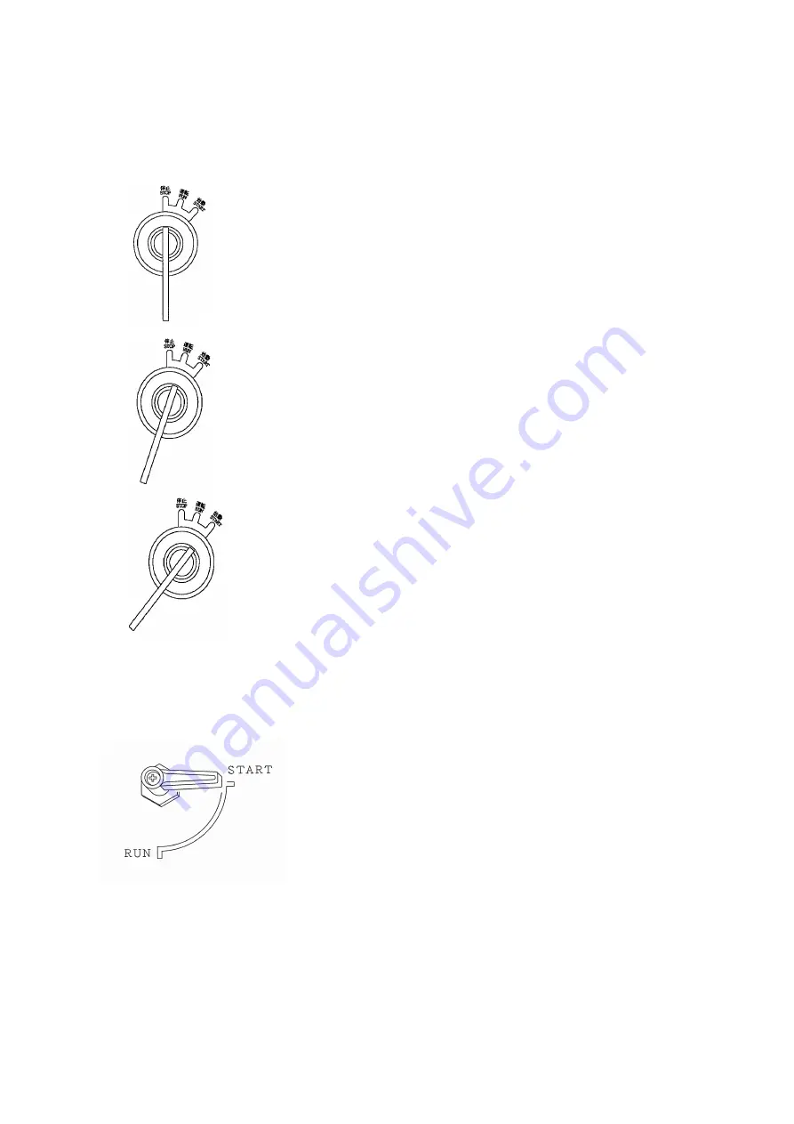
(1) Starter
switch
Functions:
①
STOP
This
switch
should
be
set
in
this
position
unless
the
machine
is
in
operation.
The
key
can
be
inserted
or
pulled
out
in
this
position.
②
RUN
This
switch
should
be
set
in
this
position
when
the
machine
is
in
operation.
③
START
This
is
the
position
to
start
the
engine.
When
your
hand
is
released
from
the
key
after
starting,
it
is
automatically
set
to
the
"RUN"
position.
(2) Unloader
valve
Functions:
①
START
This
is
the
position
to
start
the
engine.
When
engine
start,
warming
up
the
engine
for
5
to
10
minutes
at
the
this
position.
②
RUN
After
warming
up
the
engine
,set
the
unloader
valve
to
the
"RUN"
position.
You
can
use
delivered
air
by
compressor
Summary of Contents for DIS-390ES
Page 58: ...55 10 2 Outline drawing DIS 390ES...
Page 59: ...56 DIS 390ES trailer type...
Page 60: ...57 DIS 390ES C...
Page 61: ...58 DIS 390ES C trailer type...
Page 62: ...59 DIS 390ES D...
Page 63: ...60 DIS 390ES D trailer type...
Page 64: ...61 10 3 Combined Piping Diagram DIS 390ES...
Page 65: ...62 DIS 390ES C...
Page 66: ...63 DIS 390ES D...
Page 67: ...64 10 4 Engine wiring diagram...


