15
5 Assembly - Disassembly
Disassembly:
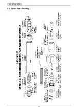
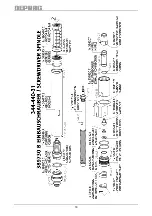
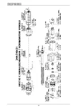
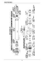
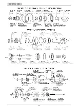
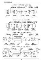
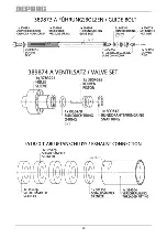
(see Spare Parts Drawing)
Prior to disassembly, disconnect equipment from air
supply! Only experienced maintenance personnel may
assemble or disassemble this equipment.
After repair or maintenance, verify that equipment runs to specification!
Principally, use only DEPRAG original spare parts. Otherwise, a reduction
in equipment power-output and an increased maintenance-requirement
occurs. If NON-DEPRAG parts are installed, DEPRAG is justified to void
any existing warranty and liability obligations.
Attention:
Motor- and gearing parts may be damaged if dropped!
For
disassembly
proceed in the sequence described below:
1. Disconnect screwdriver from air supply.
2. Unscrew clutch bearing resp. gearing complete with the attached com-
ponents (see chapter
Range and Exchange of Clutch Spring
).
3. Remove clutch complete.
4. Disassemble guide bolt by removing hex. nut 800679 (AF 17).
5. Chuck screwdriver spindle on its flange (into vice) and unscrew nipple
384207 (AF 17) and then exhaust connection 351820 T complete
(AF 36, right-hand thread).
6. Remove valve set 389874 A complete.
7. Remove valve pin 392995.
8. Hold housing at flange and use the key 462120 to remove the valve
housing 384132 (right-hand thread).
9. Pull off flange 3841571.
10. Remove the wedge 326946 by means of assembly pin 460744.
11. Push the motor- and gearing parts carefully out of the motor housing in
direction of the air inlet using a suitable arbor.
Summary of Contents for 344-340-31
Page 17: ...17 5 1 Spare Parts Drawing ...
Page 18: ...18 ...
Page 19: ...19 ...
Page 20: ...20 ...
Page 21: ...21 ...
Page 22: ...22 ...
Page 23: ...23 ...
Page 24: ...24 5 2 Installation Tips for Screwdriver Spindle ...
Page 25: ...25 ...


