background image

Section 7 


Operation 


Sybaritic, Inc. 

                               Dermalife

®

 Spa-Oceana™ 2G


System 


37 


Relaxation 

Summary of Contents for Spa-Oceana 2G

Page 1: ... the Dermalife Spa Oceana 2G System Before using the Dermalife Spa Oceana 2G System please read this owner s manual thoroughly to ensure proper and safe use Copyright 2008 Sybaritic Inc All Rights Reserved 2008 206364 Rev 803U SO 10 803 4 U ...

Page 2: ... Owner s Installation and Service Manual Voice Direct Dial 952 888 8282 Toll Free 800 445 8418 Fax 952 888 8887 Web Site http www sybaritic com E mail info sybaritic com SYBARITIC INC 9220 James Avenue South Minneapolis MN 55431 USA ...

Page 3: ...ase feel free to contact your Sybaritic Sales Representative or our Customer Service Department We look forward to the opportunity of offering additional products and services to you Please forward all inquiries to the address listed above or visit us at www sybaritic com In order to offer the highest quality products and services to our customers we welcome your feedback regarding your new Dermal...

Page 4: ... 5 4 Adjusting the Legs 14 5 5 Electrical Water DVD and Audio Connection Drawings 14 16 Section 6 Product Introduction 6 1 Dermalife Spa Oceana 2G System Introduction 17 6 2 Dermalife Spa Oceana 2G System Features 17 18 6 3 Dermalife Spa Oceana 2G System Contraindications 18 6 4 Water Intake 18 Section 7 Operation 7 1 The Control Panel s 19 20 7 2 Dermalife Spa Oceana 2G Component Drawings 21 7 3 ...

Page 5: ...57 9 9 Steam Generator 58 9 10 Replacing the Heating Element 59 9 11 Replacing the Thermal Fuse 59 60 9 12 Replacing the MG Anode 60 9 13 Replacing the Water Level Sensor 60 61 Section 10 Advanced Electronics and Troubleshooting 10 1 Electrical Connections 62 10 2 Other Components on the PC Board 63 10 3 Principal Water and Electrical Diagram 64 10 4 Principal Water and Electrical Component List 6...

Page 6: ...TABLE OF CONTENTS Continued Section 12 Specification Information 12 1 General 72 12 2 Supplied Accessories 73 APPENDICES Owner Record A Owner s Registration Form B Standard Warranty C ...

Page 7: ...teams are ready to assist you with a prompt response to any question communicated to us by telephone email and or fax 1 3 Disclaimer While every attempt is made to ensure the accuracy and completeness of the information in this document some errors may exist Sybaritic Inc does not accept responsibility of any kind for customer loss due to use of or reliance upon this document Sybaritic Inc reserve...

Page 8: ...r the Dermalife Spa Oceana 2G System as shown in the Appendix of this reference guide Sybaritic Inc may at its option repair or replace any parts found to be defective during said warranty period Sybaritic Inc has designed a Warranty Parts Replacement Policy to keep service as simple and timely as possible Only the major component parts of the Dermalife Spa Oceana 2G System should be replaced on s...

Page 9: ...ear of the unit or to any damage of the unit or its subparts in result of blatant misuse of the unit Limited Manufacturer s Warranty period length is 12 months Limited Manufacturer s Warranty for steam generators does not apply for defects and or malfunctions arising from water hardness Limited Manufacturer s Warranty does not cover any indirect losses and or loss of profits nor does it cover any ...

Page 10: ...censed plumber is authorized to make the plumbing installation strictly according to all local plumbing installation requirements ANY UNAUTHORIZED AND OR IMPROPER PLUMBING INSTALLATION IS STRICTLY FORBIDDEN IN CASE OF UNAUTHORIZED AND OR IMPROPER INSTALLATION THIS UNIT MUST NOT BE USED AND IT WILL RESULT IN WAIVE OF ANY TYPE OF MANUFACTURERS WARRANTY THE USE AND OPERATION OF THE UNIT MUST BE CEASE...

Page 11: ...y hot when the Radiant Heat feature is in use Do not disassemble or modify the unit Prevent flammables and metallic objects from entering the unit Do not use the unit when there is lightning in the vicinity Disconnect the power cable of connected equipment Avoid using the unit under the following conditions Places subject to excessive shock or vibration Extremely hot places Use carefully May cause...

Page 12: ...e flow rates are compatible Never operate the capsule if the suction fittings are broken or missing Never replace the suction fitting with one rated less than the flow rate marked on the original suction fitting DANGER Risk of electric shock Install at least 1 5 m 5 feet from all metal surfaces As an alternative a capsule may be installed within 1 5 m of metal surfaces if each metal surface is per...

Page 13: ...should consult a physician before using capsule since some medication may induce drowsiness while other medication may affect heart rate blood pressure and circulation CAUTION Risk of electric shock Replace audio video components only with identical components Do not operate the audio video controls while inside the capsule WARNING Prevent electrocution Do not connect any auxiliary components for ...

Page 14: ...RTED IN WINTER CONDITIONS transportation temperature below 32 F 0 C THE UNIT MUST BE STORED AT A ROOM TEMPERATURE conditions 59 to 86 F 15 to 30 C relative humidity max 95 FOR TWENTY FOUR HOURS TO BE WARMED UP BEFORE INSTALLATION AND OPERATION INSTALLING THE UNIT AND STARTING UP THE UNIT PREMATURELY WITHOUT PRIOR SLOW WARMING PERIOD MAY RESULT IN SERIOUS DAMAGE TO THE ELECTRONICS AND LCD PANEL OF ...

Page 15: ...reaker The current draw depends on the voltage and is rated at 13 41 amps for 220 volts when Radiant Heat and Steam are running The unit is designed for use in current circuits where either a neutral conductor or a stationary protective conductor with equivalent potential is available system TN S It is strictly prohibited to use the unit in alternating current circuits TT and IT Unit electrical sp...

Page 16: ...ntee that it is necessary to install mechanical water filters 50 micron filtering Filters must have a flow rate of 2 5 gallons 9 5 liters per minute All other water supply characteristics must meet the local drinking water requirements Water supply connections in capsule are for water inlets and the drain is 40mm BOTH THE COLD AND HOT WATER SUPPLY MUST HAVE SHUTOFF OPEN CLOSE VALVES THAT WOULD ENA...

Page 17: ...liters assuming a 50 50 mix of hot and cold water this equates to approximately 30 gallons 110 liters of hot water per tub session The steam shower system and the tub are used as separate sessions NOTE Only a qualified certified licensed plumber is authorized to make the plumbing installation strictly according to all local plumbing installation requirements ...

Page 18: ...ls BEFORE ANY REPAIR AND OR INSPECTION OF THE UNIT THE ELECTRICAL SUPPLY MUST BE SHUT OFF BEFORE REMOVING THE SIDE PANEL OF THE UNIT SHUT OFF THE ELECTRICAL SUPPLY TO THE UNIT To remove the right side panel remove screws S1 S2 S3 S5 S6 S7 S8 and S4 S3 and S4 have two 2 screws on the opposite side panel S1 S7 S3 S4 S5 S6 S2 S8 5 2 Removing the Hood Cover Remove two 2 screws and pull the cover in th...

Page 19: ...valves in the hood Disconnect all cables and wires Disconnect water quick connections by pressing the opening ring while at the same time pulling the male end in the direction of the arrow To reconnect the quick connections press the male portion of the fitting into the female portion of the fitting Open capsule and unscrew strut nuts while keeping the capsule open Remove strut nuts and close caps...

Page 20: ...th black cable 0 5 m is located beside the circuit breaker box DVD Connection 2G machines are equipped with video and audio inputs 3 male RCA connectors The input cables are located on the right side of the machine under the side cover Color code for connecting the external audio video device o Yellow composite video input o Red right audio channel input o White Black left audio channel input To u...

Page 21: ... audio source Audio can be activated and adjusted as described in the Operation section Please see additional information on plumbing and electrical installation in Requirements for Plumbing and Installation and Requirements for Electrical Supply and Installation Audio connection plug 3 5 mm with black cable 0 5 m is located beside the electronics box DISCONNECT CAPSULE FROM ELECTRIC SUPPLY BEFORE...

Page 22: ...tallation Drawings ____________________________________________________________________________________________ Sybaritic Inc Dermalife Spa Oceana 2G System 16 Spa Oceana general measurements 2200 mm 1050 mm 840 mm ...

Page 23: ...tures The features of your Spa Oceana 2G are listed below We have created preset programs for ease of use and maximum efficiency each program has a different blend of Spa Oceana 2G features To maximize versatility and creativity for spa owners a custom program is also available for you and or your clients to create unique combinations of the Spa Oceana 2G features Translucent Shell 10 Vichy Shower...

Page 24: ...elaxed flotation and air suspension Vibration is adjustable and offers both continuous and pulsation modes 6 3 Dermalife Spa Oceana 2G System Contraindications Knowledge of your client s contraindications requires a thorough client analysis Being unaware of their medical history may cause problems Heart respiratory problems High blood pressure Kidney disorders Nervous conditions e g epilepsy Pregn...

Page 25: ...s which are mounted on the console for the user and on the mounted panel for the operator are used to operate the Spa Oceana 2G System Pressing a membrane keypad on the panel enters commands The LCD Display shows the status of the operations being performed Control Panel 1 Up 2 Right 3 Down 4 Left 5 Escape no 6 Enter yes 1 2 3 4 5 6 Figure 1 ...

Page 26: ...ection 7 Operation Sybaritic Inc Dermalife Spa Oceana 2G System 20 Bath Control Panel Back and Foot Jets Hand Held Jets pump 1 Color Lights Counter Side Jets pump 2 Speed control Program buttons Figure 2 ...

Page 27: ...op view Electronically controlled jet valves 10 Hot Cold Jets 6 Color Light Lamps 4 in hood Foot Jets 4 Foot Jets 8 hydro jets Hand Jet 3 additional hydro jet air regulators Jet diverter between foot and back 2 hydro jet pumps 8 back jets Foot jet air control Side jet air control Back jet air control Connector for hand jet 4 foot jets 8 back jets Jet diverter between foot and back ...

Page 28: ...residue that might be remaining in the water ducts 7 4 How to Run Your First Warm Up Session Main Menu PROGRAMS WARM UP SETTINGS SERVICE LANGUAGE INSTALL 07 00 Ent Esc Select the Warm Up Option Select the Warm Up program with the motion buttons UP DOWN LEFT RIGHT until Warm Up blue box is highlighted Confirm your selection by pressing ENTER see Figure 1 The Spa Oceana 2G System automatically warms...

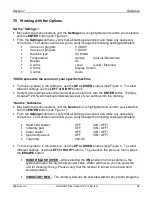
Page 29: ...he ENTER button The Spa Oceana 2G System will automatically save all of your settings into the memory Service Submenu Move with the motion buttons until the Service box is highlighted and confirm your selection with the ENTER button see Figure 1 From the Settings submenu verify that all settings are correct and make any necessary corrections The submenu will allow you to verify change the followin...

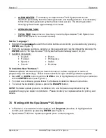
Page 30: ...languages English Russian Spanish French Polish Portuguese Italian Estonian To Install the New Software Software updates will ensure that you have the most up to date equipment in terms of programming and technology Follow these instructions upon receiving software upgrades Move UP or DOWN buttons until the INSTALL box is highlighted and confirm your selection with the ENTER button see Figure 1 To...

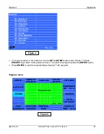
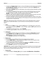
Page 31: ... move up down in the submenu use the UP or DOWN buttons see Figure 1 Press ESCAPE to go back to the previous menu To select the program press the ENTER button Press ENTER to start the selected Spa Oceana 2G program Program menu AUDIO DISPLAY CONTROL FACE AIR COLOR LIGHTS VIBR BED DRY HEAT Program 02 TEMPERATU RE 25 o C STEAM AROMAS Ent Esc VICHY SHOWER FOOT MASSAGE SCOTTISH SHOWER TROPICAL RAIN SE...

Page 32: ... DRY HEAT dry heat could be turned ON OFF a Audio Insert music or instructional CD into DVD player Press play on DVD player The audio signal will immediately be sent to the spa unit Activate the Audio function on the LCD display by pressing the motion buttons UP DOWN LEFT RIGHT and make your selection by pressing the ENTER button see Figure 1 To Increase or Decrease volume select the volume contro...

Page 33: ...the spa for a treatment session c Steam To activate the Steam function select the ON position in the Steam menu and confirm your selection by pressing ENTER To shut off Steam select the OFF position from the Steam menu To get back to the Program Menu press ESCAPE The ideal range for Steam is from 110 to 118 F 43 to 47 C d Temperature To select the desirable steam sauna temperature activate the Tem...

Page 34: ...EFT or RIGHT buttons until your desired interval is reached To turn OFF vibration in either mode choose OFF from the Vibratory Bed submenu Turn ON OFF vibration bed and confirm your selection by pressing ENTER g Face Air To turn on the fan highlight the Face Air function field and press ENTER To control intensity in this mode press LEFT or RIGHT buttons in the Face Air submenu until your desired l...

Page 35: ...system NOTE Regarding Aroma Oils 1 Essential oils must NOT be used in the aroma reservoir 2 Use ONLY the Oxygen Science Concentrates that come with the unit These are water based aromas 3 Use of pure essential oils within the aroma diffuser tank WILL CAUSE DAMAGE to the plastic tank and flow valve j Tropical Rain To turn on the Tropical Rain function highlight it on the Program Menu by using the m...

Page 36: ... selections from the MODE submenu 3 modes Confirm your selection by pressing ENTER To select a comfortable alternating interval for the jets select the section INTERVAL in the Vichy Shower submenu Adjust the interval by using LEFT or RIGHT buttons and confirm your selection by pressing ENTER To get back to the Program Menu press ESCAPE NOTE Vichy Shower cannot be selected in conjunction with other...

Page 37: ... somewhere in between the two for moderate airflow c Back Jet and Foot Jet Hand Held Jet To activate the Back Jet function press the Back Jet button from bath control panel figure 2 To split the water flow between the Back and Foot Jets turn the diverter positioned at left hand to the desired position To control the amount of air coming through the jets turn the round dial s to MIN MAX or somewher...

Page 38: ...bath session refer to section 7 6 7 9 Safety Shut Off If you open the Spa Oceana 2G System s cover during the session the steam radiant heat and all water systems will switch off automatically 7 10 Stopping Your Session You can stop and reset your session at any time by pressing the CANCEL button and following the instructions on LCD display 7 11 Turning Off Your Spa Oceana System It is not necess...

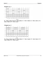
Page 39: ...Section 7 Operation Sybaritic Inc Dermalife Spa Oceana 2G System 33 Hydro Working Charts ...

Page 40: ...Section 7 Operation Sybaritic Inc Dermalife Spa Oceana 2G System 34 ...

Page 41: ...Section 7 Operation Sybaritic Inc Dermalife Spa Oceana 2G System 35 7 12 1 Capsule Device Pre Set Programs Working Charts High Heat ...

Page 42: ...Section 7 Operation Sybaritic Inc Dermalife Spa Oceana 2G System 36 Cleansing ...

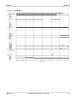
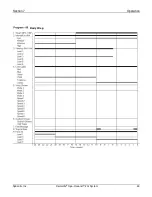
Page 43: ...Section 7 Operation Sybaritic Inc Dermalife Spa Oceana 2G System 37 Relaxation ...

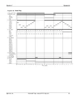
Page 44: ...Section 7 Operation Sybaritic Inc Dermalife Spa Oceana 2G System 38 Aquatica ...

Page 45: ...Section 7 Operation Sybaritic Inc Dermalife Spa Oceana 2G System 39 Muscle Care ...

Page 46: ...Section 7 Operation Sybaritic Inc Dermalife Spa Oceana 2G System 40 Smoothing ...

Page 47: ...Section 7 Operation Sybaritic Inc Dermalife Spa Oceana 2G System 41 Escape ...

Page 48: ...Section 7 Operation Sybaritic Inc Dermalife Spa Oceana 2G System 42 Sleep Meditation ...

Page 49: ...Section 7 Operation Sybaritic Inc Dermalife Spa Oceana 2G System 43 Body Wrap ...

Page 50: ...Section 7 Operation Sybaritic Inc Dermalife Spa Oceana 2G System 44 Hot Cold ...

Page 51: ...ench 10mm 13mm and two people Removal a Remove panels and hood cover b Disconnect water quick connections between hood and base c Disconnect electrical wires d Open capsule and unscrew strut nuts e If you are changing the struts install new instead of old f For hood removal close capsule and remove hinge pins using punch and hammer Installation a Install hinge pins b Open capsule and connect strut...

Page 52: ...Section 8 Service Hood Sybaritic Inc Dermalife Spa Oceana 2G System 46 8 3 Principle Water Diagram with Valve Connections ...

Page 53: ...connection E4000 29 Modular electrovalves 6 way E4000 15 8 5 Water Jet Required tools screwdriver large pliers pipe coil silicone Removal a Disconnect tube b Remove fixing nut c Large pliers will probably be needed for this Installation a Place housing through hood and put silicone as shown in figure b Tighten fixing nut c Connect tube There are 2 pipes on jet housing 1 is closed and 1 is open Be ...

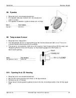
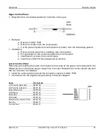
Page 54: ...nnect wires b Remove screws and remove parts as shown in the figures in below Installation a Install parts as shown in the figure below b Connect wires NOTE When replacing screws use stainless screws Name Part Number Mist jet E4000 12 Elbow Name Part Number IR emitter E4000 19 Reflector E4000 20 Reflector gasket E4000 21 Glass E4000 22 Glass gasket E4000 23 IR flocked cover E4000 24 Screw fixing r...

Page 55: ...hrough the hood and secured with a nut The nut is round and pliers are required for its removal The sensor is connected to LCDrb in LCD housing See Opening the LCD Housing and Replacing Parts in the LCD Housing on the following pages for information on disconnecting wiring 8 10 Opening the LCD Housing Required tools crosshead screwdriver Move LCD housing position as shown in the figure below Remov...

Page 56: ...Section 8 Service Hood Sybaritic Inc Dermalife Spa Oceana 2G System 50 Principal scheme of devices in hood ...

Page 57: ...connectors from the LCDrb PCB b Remove two screws from the LCDrb PCB and take off LCDrb PCB c Cut glue in edges of LCD panel d Remove two screws from LCD mounting bracket and carefully remove LCD display from housing Installation a Put LCD panel into position and put some glue drops at the bottom corners b Install the two 2 screws into the LCD mounting bracket c Put LCDrb PCB into position and ins...

Page 58: ...l d Install the LCDrb PCB and fasten all connectors Lower Control Panel Removing and installing the lower control panel is the same as the upper control panel with one difference the control panel plug is larger than the holes Replacement control panels are sent with the connector not installed Install the control panel and route the connection cable to LCDrb PCB Insert wires into the supplied plu...

Page 59: ...ANEL OF THE UNIT SHUT OFF THE ELECTRICAL SUPPLY TO THE UNIT To remove the right side panel remove screws S1 S2 S3 S5 S6 S7 S8 and S4 S3 and S4 have two 2 screws on the opposite side panel 9 2 Drainage The drain is on the floor of the hydrotub An overflow drain is located on the side of the hydrotub as shown in the drawing to the right The smell lock has a 40 mm tube All tubes are usually 40 mm Nam...

Page 60: ...em electrical diagram Name Part Number Aroma tank upper E4000 109 Aroma tank lower E4000 108 Level sensor E4000 93 9 4 Mineral Vitamin System The mineral vitamin system is shown in the figure to the right When the massage jets lose pressure the basket in the mineral vitamin system must be cleaned To clean the basket remove tubs and corpus Name Part Number Vitamin apparatus lower E4000 105 Vitamin ...

Page 61: ...Section 9 Service Bottom Sybaritic Inc Dermalife Spa Oceana 2G System 55 9 5 Vibratory Bed Required tools crosshead screwdriver knife wire cutters wire strippers wire crimper silicone ...

Page 62: ...wo 2 screws from the filter bracket and remove bracket to remove the filter Remove four 4 screws from the motor brackets Remove the brackets to remove the motor If replacing bed remove cable from the nest to use in new bed Install motor and filter in reverse order of removal procedure When installing cover make sure to apply silicon around the edge of the cover to ensure watertight seal to the nes...

Page 63: ...minal 37 11 5V Terminal 39 is ground in the main power box See the 10 1 Electrical Connections table Power Supply The power supply input is connected to 220V at the main circuit breaker The output is connected to terminal 36 15V Terminal 38 9V and terminal 39 are ground See the 10 1 Electrical Connections table The small green LED is on when the Power Supply works correctly If the LED is not on re...

Page 64: ...king with the steam generator always disconnect capsule from power supply The generator is connected with two 2 screws Wires are not displayed in the figure Nuts are in metric system Electrical Diagram of Steam Generator NOTE When you are working with the steam generator always disconnect capsule from power supply ...

Page 65: ...heating element out Installation a Loosen securing nut and push the heating element securely into the steam generator Tighten the securing nut approximately three 3 turns b Install wires from cable 3 onto the heating element See steam generator electrical diagram c Close protective cover d Install the two 2 nuts and tighten the cable grip nuts 9 11 Replacing the Thermal Fuse Required tools small f...

Page 66: ... Installation a Place heat resistant silicone around the collar of the anode b Push the anode all the way into the mount and install the screw that holds the anode into the mount NOTE It may be necessary to remove the two 2 screws that hold the steam generator in order to tilt the generator to allow the anode to be removed 9 13 Replacing the Water Level Sensor Required tools large pliers heat resi...

Page 67: ...ermalife Spa Oceana 2G System 61 NOTE If you change water level sensor check that the thermal fuse and heating element are in proper working order Name Part Number Water level sensor 302240 08 Thermal Fuse 302240 07 Heating Element 302240 38 ...

Page 68: ...een Aroma level sensor 19 7 White Aroma 8 51 Black 8 Yellow 52 Red Speaker 20 9 Brown green 53 Audio line In 10 Gray 54 Headphones 11 Blue 55 Blue 12 White Main water Hand shower Hot cold Gen fill 9 56 Brown Gen Thermal melting fuse 4 13 Brown U0 Blue 14 Brown U1 Brown IR emitter 2 15 White Drain 10 L Brown 16 Pink N Blue Mains 1 17 Blue U2 Blue 18 Gray U3 Brown 19 Green GND Steam 3 20 Brown Bath ...

Page 69: ...Section 10 Advanced Electronics and Troubleshooting Sybaritic Inc Dermalife Spa Oceana 2G System 63 10 2 Other Components on the PC Board ...

Page 70: ...Section 10 Advanced Electronics and Troubleshooting Sybaritic Inc Dermalife Spa Oceana 2G System 64 10 3 Principal Water and Electrical Diagram Shower Hot Cold Foot jets ...

Page 71: ...Section 10 Advanced Electronics and Troubleshooting Sybaritic Inc Dermalife Spa Oceana 2G System 65 10 4 Principal Water and Electrical Component List ...

Page 72: ...Wall faucet is closed Open wall faucet Generator filling valve faulty Check control valve connections Service may be required WATER TANK EMPTY Spa Oceana 2G steam generator did not get the water during 25 seconds from injection valve opening Water pressure loss Check the water filter for proper operation HEATER COMBUSTION Heater fault The steam generator thermal fuse is blown Thermal fuse is blown...

Page 73: ...city Control main fuse and CGFI Control ON OFF switch Hard to open hood hood falls down easily Bumpers are old Replace bumper s Radiant Heat panel doesn t work Check panel connections All Radiant Heat panels do not work Check panel connections Check fuse F1 on PC board IR fuse If fuse is blown and new fuse blows there may be a short circuit in the chain Check all wires and panels If fuse is correc...

Page 74: ...e effective and environmentally friendly Facts about ACCEL TB a Effective cleaner b Effective disinfectant c Highly efficient only requires soaking on the material for 1 minute as opposed to traditional cleansers whose warnings require up to 10 minutes for total disinfecting d Non toxic e Non corrosive this relates to the skin eye as well as surfaces f Biodegradable Certifications for the Product ...

Page 75: ...SIBILITIES The Customer is responsible to Use ONLY the SYB approved Accel TB Cleaning Solution Use of any and all other cleaning products for cleaning and disinfecting your unit will immediately void your product warranty covering the Polycarbonate material on the machine 11 2 Cleaning the Shell Your Spa Jet 2G System is shipped to you wrapped carefully in clear plastic wrap The plastic wrap will ...

Page 76: ...cosmetics It will also prolong the material life of the accessories and bed 11 5 Cleaning the Steam Generator 11 5 1 Steam Drainage Process Recommended to be completed daily 1 Turn the system On 2 Press Enter to continue 3 Use arrow keys to move to and highlight Service feature and press Enter 4 Scroll down with arrow keys until Drainage feature is highlighted 5 Press right arrow key to open drain...

Page 77: ...an Note This process can be completed with tap water 11 7 Cleaning the System Drain Located under the upper vibratory bed Recommended to be completed nightly 1 Carefully unplug the upper and lower vibration beds The plugs must be unlocked counterclockwise before removing male from female connectors 2 Remove the bed section and set off to the side of the machine 3 Use Accel disinfectant and dry tow...

Page 78: ...m Water inlet G Required water pressure 1 5 4 bar Electric appliances Voltage 200 230 V Amperage 15 A 25 A Frequency 50 60 Hz Tub appliances Hand shower 1 Vichy massage jets 10 Foot massage jets 2 Tropical rain jets 2 Bath back massage jets 10 Bath side massage jets 8 Bath foot massage jets 4 Underwater hand massage 1 Additional appliances Massage shower programs 10 1 Custom Program Steam generato...

Page 79: ...t cold face mask Dermalife Systems Training DVD 1 Spa Oceana 2G System Owner s Manual 1 Oxygen Science Vitamin Concentrate 16 9 oz bottle 1 Oxygen Science Mineral Concentrate 16 9 oz bottle 1 Oxygen Science Wellness Concentrate 16 9 oz bottle Accel TB Disinfectant 32 oz Accel TB Sprayer NOTE Supplied accessories are subject to change Contact your supplier with questions ...

Page 80: ...No USA HEADQUARTERS DISTRIBUTED BY SYBARITIC INC 9220 JAMES AVENUE SOUTH MINNEAPOLIS MN 55431 USA Tel 952 888 8282 Fax 952 888 8887 WARNING TO PREVENT FIRE OR SHOCK HAZARD 1 DO NOT EXPOSE UNIT TO RAIN 2 DO NOT PLACE THE UNIT IN A SHOWERING AREA OR STEAM ROOM CAUTION TO REDUCE RISK OF ELECTRICAL SHOCK DO NOT REMOVE COVER OF THE ELECTRICAL BOX INSIDE UNIT OR THE FACE PANEL NO USER SERVICEABLE PARTS ...

Page 81: ...to Sybaritic Sybaritic Inc 9220 James Avenue South Minneapolis MN 55431 USA Tel 952 888 8282 800 445 8418 Fax 952 888 8887 Serial Number Date of Purchased Model Number Business Name Owner s Name Mailing Address City State Country Telephone Fax Purchased From Name Mailing Address City State Country Telephone Fax Cut out along this ...

Page 82: ... is to be prepaid by customer Sybaritic will pay for the return of the freight to the customer On site service as required on site labor is provided for diagnosis and repair of affected equipment This service will be scheduled at the earliest opportunity that our assigned technician can provide GENERAL EXCLUSIONS 1 This warranty shall not cover products which have been altered replaced or which ha...

Page 83: ...ge All replacement defective parts must be returned to Sybaritic freight pre paid by the Warranty Owner Sybaritic Technical Service will provide the Owner with a Return Goods Authorization Number for the return Return parts not received by Sybaritic Inc within 30 Days will constitute cause for invoicing of the replacement parts to the Product Warranty and Extended Warranty Owners at list price Pro...

Page 84: ...Owner s Notes ...

Reviews: