EX, SGX VIBRATOR MOTORS
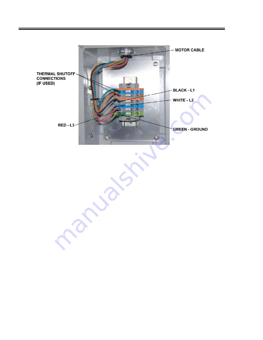
Figure 7 Junction Box Electrical Connections - Single Motor
Motor Thermal Switch Connections
If desired, the thermal switch embedded in the motor’s stator winding may be connected to turn
on an indicator to inform personnel that the motor is operating within the normal temperature
range. Alternatively, the switch may be connected to an overload protection device in the motor
starter box to shut down the motors in case of high stator temperature. To permit connection to an
external device, the blue and orange leads from the thermal switch are brought out to terminals
P1 and P2 in the equipment electrical junction box. To wire the thermal switch, connect leads from
the external indicator and power source to terminals P1 and P2 in the junction box.
If the stator temperature becomes abnormally high, the normally closed (N.C.) thermal switch
contacts open. Depending on the connection scheme, the open contacts either turn off the
indicator or shut down the motor(s). The indicator and power source are customer-supplied.
Motor Test
After completing the electrical connections, test the motor to confirm proper operation. For dual-
motor installations check that motors rotate in opposite directions. Reverse the leads of one motor
to correct the direction of rotation, if necessary.
16
01 May 09
Summary of Contents for EX
Page 2: ......
Page 4: ......
Page 6: ......
Page 17: ...EX SGX VIBRATOR MOTORS Figure 2 Motor Cord Connections to Terminal Block 01 May 09 11 ...


