11
102553
(Pump Rotor, continued)
10.Install blades, pump plate, air filters,
and filter end cover.
11.Replace fan guard and upper shell.
12.Adjust pump pressure (see page 9).
Note:
If rotor is still binding, proceed as
follows.
13. Perform steps 1 through 6 (see page 10).
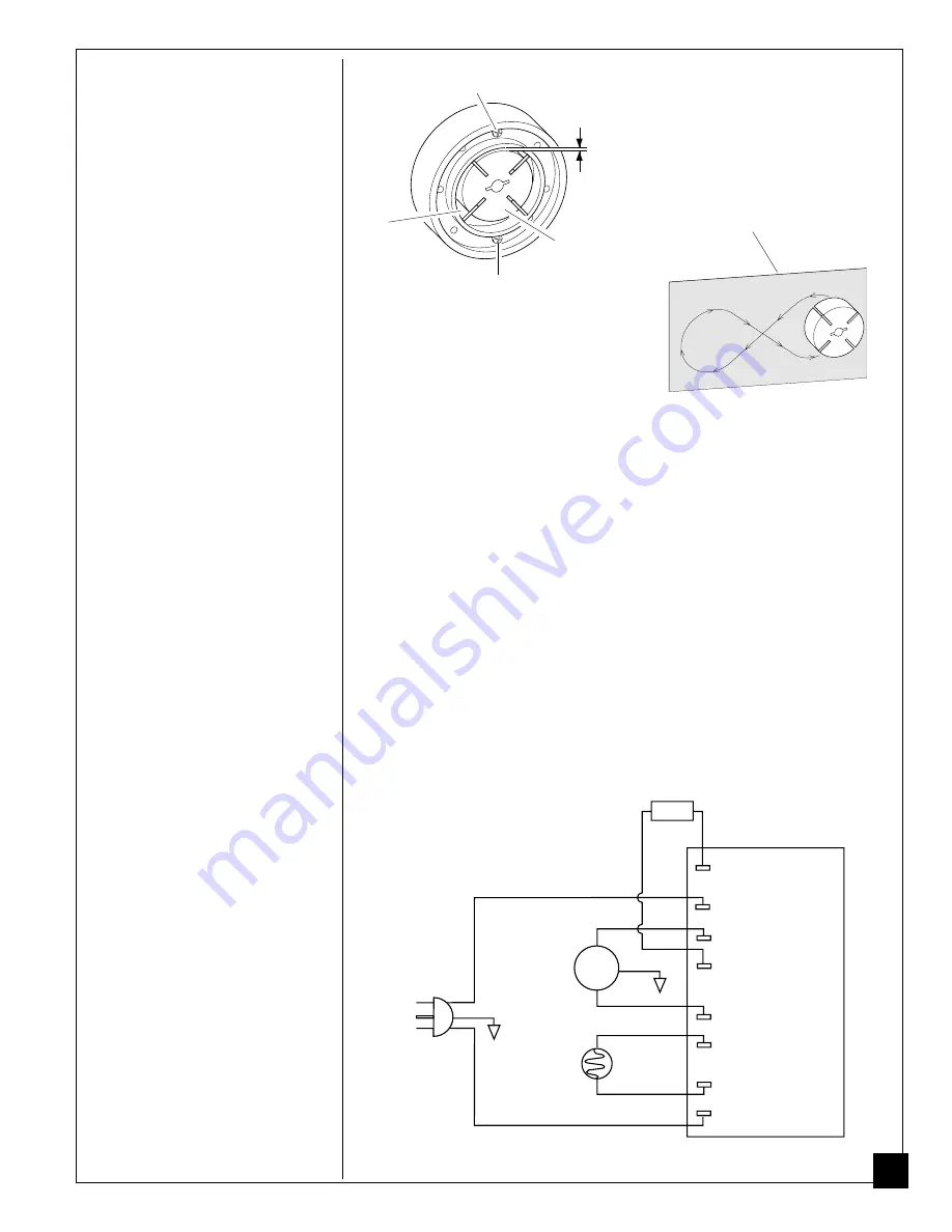
14. Place fine grade sandpaper (600 grit)
on flat surface. Sand rotor lightly in
“figure 8” motion four times (see Fig-
ure 14).
15.Reinstall insert and rotor.
16.Perform steps 10 through 12 above.
Sandpaper
Figure 14 - Sanding Rotor
.003"/.004" Gap
Measured With
Feeler Gauge
Blade
Rotor
Gap Adjusting Screw
Gap Adjusting Screw
Figure 13 - Gap Adjusting Screw Locations
SPECIFICATIONS
Output Rating (Btu/Hr.)
50,000
Fuel
Use Only Kerosene or No. 1 Fuel Oil
Fuel Tank Capacity (U.S. Gal.)
4.0
Fuel Consumption (Gal. Per Hr.)
.40
Electric Requirements
120 V/60 Hz
Amperage (Normal Run)
2.0
Motor RPM
1725
Hot Air Output (CFM)
175
Pump Pressure (psi)
3.6
Shipping Weight (Approximate Pounds
35
Heater Weight without Fuel
(Approximate Pounds)
30
Figure 16 - Wiring Diagram
WIRING
DIAGRAM
Blue
Photocell
Power Plug
120V/60Hz
Ignitor
Ignitor
Blue
White
Red
Gray
Gray
Green
Motor
White
Black
AC Common (L2)
Photocell
Photocell Common
Motor Common
Motor
AC Hot (L1)
Ignitor Common
Ignition Control
Green


