background image

www.desatech.com

115423-01A

6

CAUTIONS

1.  Before servicing, disconnect the heater from 

the electrical power source by removing the 

electrical plug from the wall receptacle.


Note:

 When certain tests require electrical power 

to be applied, connect electrical power only for 

the time necessary to complete the test.

2.  Do not bypass safety devices except when 

instructed  to  do  so  during  troubleshooting 

procedures.

3.  If  replacement  parts  are  necessary,  do  not 

substitute with non-factory parts (use only 

factory authorized replacement parts).

4.  Make sure all electrical connections are secure 

and correct prior to connecting heater to a 

grounded electrical power source. 

ALL SYSTEMS WORKING 

TOGETHER

There are three basic systems within the heater, the 

heating system, air system and safety system.
A  tubular  heating  element  (A)  warms  the  sur-

rounding air.
A fan (B) on one end of a motor (C) draws air into 

the product. This air is directed over the heating 

element to create warm heated air out.
An over temperature switch (D) shuts the heater off 

in the abnormal event a motor were to fail.
A tip over switch (E) shuts the heater off in the 

event the product is tipped over.
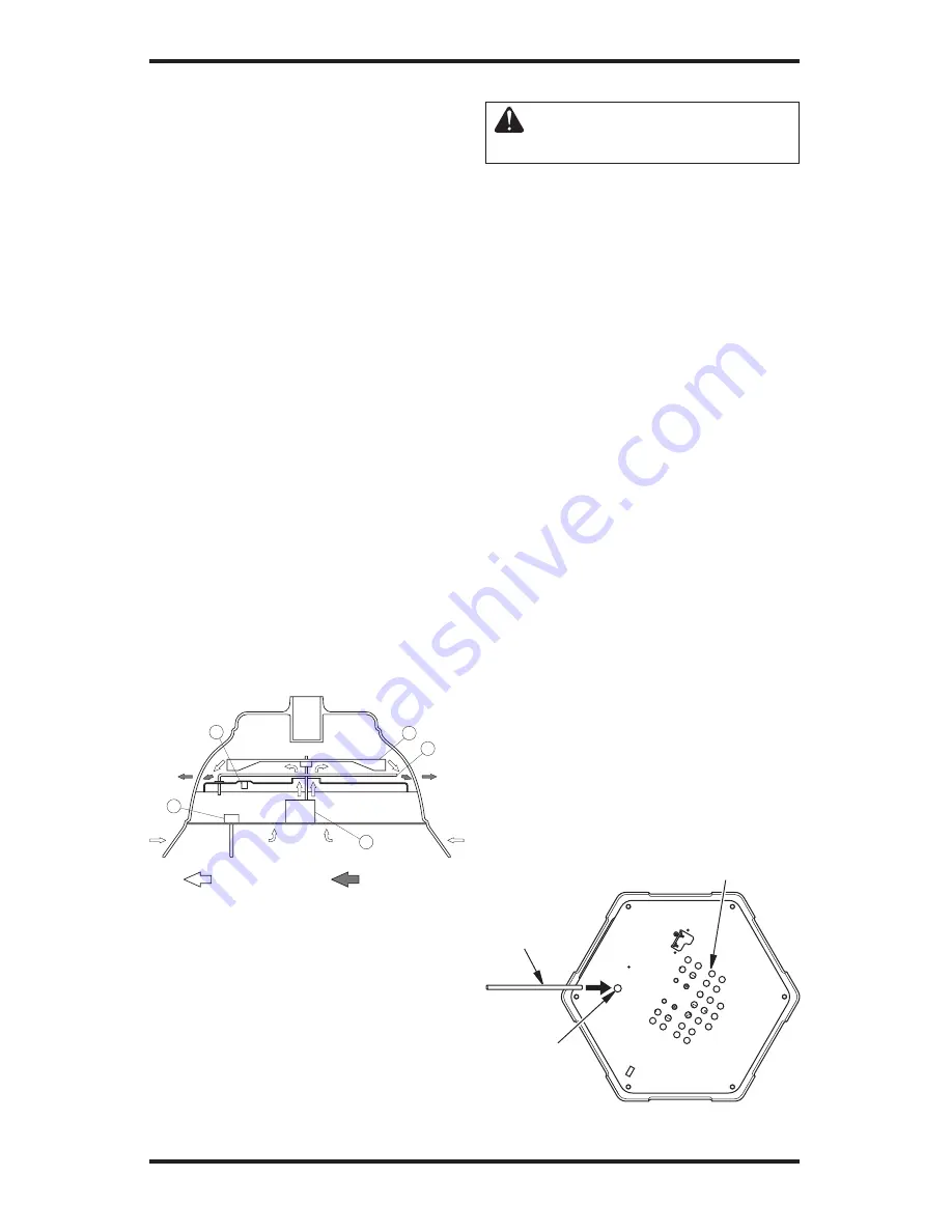
Access to 
Thermal 
Limit Switch

Figure 5 - Resetting Thermal Limit Switch

Push Rod

INSPECTION

Check for damage in the following ways:
1.  Examine exterior of plastic shroud and inside 

pole receiver for cracks. Replace shroud if 

cracks are found.

2.  Examine cover of on/off switch for cracks. 

Replace switch if cracks are found.

A

C

Air To Be Heated

Heated Air

D

E

B

Figure 4 - System Operation

TROUBLESHOOTING

  CAUTION:  Risk  of  electric 

shock.

If your product fails to operate:

1.  Make sure the electrical outlet GFCI or circuit 

breaker and extension cord is working. 

2.  Check for operation of tip switch. The ON/

OFF switch light can be on but the tip switch 

OFF. Move product until a “click” is heard. 

To prevent damage of tip switch post, do not 

slide product.

3.  Look for obstructions around fan. If you find 

an  obstruction,  turn  the  product  OFF  and 

UNPLUG THE PRODUCT. Have the product 

serviced by a qualified individual.

4.  Check for tripped thermal protector. Motor 

and heating element do not operate. Wait 10 

minutes for product to cool. Push reset button. 

See 

Thermal Limit Switch

 below.

THERMAL LIMIT SWITCH

If product is used in temperatures below 75° F 

(28.9°  C),  the  limit  switch  should  not  require 

resetting unless there is a malfunction. If a mal-

function does occur, have the product serviced by 

an authorized service center.

Resetting Thermal Limit Switch

1.  Unplug product.
2.  Allow product to cool.
3.  Turn product upside down.
4.  Remove plug on bottom.
5.  Insert provided plastic push rod through hole 

and  guide  to  small  red  button  on  thermal 

limit switch (see Figure 5). A flashlight will 

improve visibility.

6.  Lightly push red button to reset switch.

Air Intake Openings

Summary of Contents for PD15EA

Page 1: ...erence For more information visit www desatech com MODELS PD15EA PG15EA PL15EA AND PV15EA 1500 WATT 120V 60HZ 12 5 AMPS OUTDOOR ELECTRIC PATIO TABLE UMBRELLA STAND AND FOOT WARMER SERVICE MANUAL TABLE OF CONTENTS Safety Information 2 Pre Operating Instructions 3 General Information 4 Product Identification 5 Installation 5 Operation 5 Cleaning 5 Wiring Diagram 5 Safety Requirements 6 Cautions 6 All...

Page 2: ...ug product after use 13 When unplugging be sure to pull by the plug and not the cord 14 Keep electrical plug dry and off of wet surfaces 15 Do not place or store where product can fall or be pulled into swimming pool or body of water If product falls into water unplug immediately DO NOT REACH INTO WATER If water is above the air intakes see Figure 3 page 4 or product is totally immersed in water d...

Page 3: ...er or birth defects or other reproductive harm PRE OPERATING INSTRUCTIONS GROUND FAULT INTERRUPTER Since 1971 the National Electric Code NEC has required Ground Fault Circuit Interrupter devices on all outdoor circuits Ifyourresidencewasbuiltbefore1971 checkwith a qualified electrician to determine if a Ground Fault Circuit Interrupter protector exists Do not use this product if the circuit does no...

Page 4: ...ise which have not been covered If such problems arise please call the Technical Service Departmentʼs number 1 866 672 6040 or visit our website at www desatech com to address these technical problem areas If you need assistance for ordering parts billing questions etc you should contact 1 866 672 6040 SERVICE PREPARATION A clean work area at the start of each job is essen tial for efficient servic...

Page 5: ...Follow all local ordinances and codes when using this product 1 Push lighted ON OFF switch 2 The power light will remain lit during operation 3 Stay back from product until all water or debris has blown clear 4 Product will warm in a few minutes CLEANING DURING SEASON CARE Always unplug the product before moving or cleaning 1 Do not disassemble Carefully wipe the exte rior of unit with a soft damp...

Page 6: ...rior of plastic shroud and inside pole receiver for cracks Replace shroud if cracks are found 2 Examine cover of on off switch for cracks Replace switch if cracks are found A C Air To Be Heated Heated Air D E B Figure 4 System Operation TROUBLESHOOTING CAUTION Risk of electric shock If your product fails to operate 1 Make sure the electrical outlet GFCI or circuit breaker and extension cord is wor...

Page 7: ...il If the resistance is not approximately 6 0 to 6 4 ohms at 73 F the motor is defective and should be replaced Note Resistances may vary due to motor temperature Figure 6 Testing Motor OBSERVED FAULT Motor starts and runs but cool air is felt Does tubular heating element heat up No Yes WARNING WARNING Hot Surface Hot Surface 1 Look for defective 3 Check for blocked tubular heating air intake open...

Page 8: ...0 F such as Loctite Thread Locker Blue to each of the thermal reset switch mounting screws see Figure 10 Torque screws to 6 to 9 inch pounds 4 The tip switch cover must isolate tip switch from metal base as shown in Figure 11 5 To complete grounding of heater all ground wires must be fixed with screws as originally assembled by the manufacturer Additionally internal tooth washers must be against th...

Page 9: ... on flat of shaft see Figure 15 9 Heater is equipped with heat reflective tape If loose or damaged replace tape as shown in Figures 16 and 17 Tape edge should touch top of louver openings REASSEMBLY POINTS Continued Figure 14 Heating Element and Bracket Figure 15 Fan and Motor Figure 16 Reflective Tape and Louvers Figure 17 Reflective Tape on All Louvers Motor Shaft Back of and Flat of Motor Shaft Fan...

Page 10: ...tech com 115423 01A 10 ILLUSTRATED PARTS BREAKDOWN 19 1 7 28 14 16 9 8 2 17 18 27 26 15 Requires Loctite Thread Locker Blue 6 3 22 23 20 13 11 10 21 2 12 24 25 Steel Nut Brass Washer Rubber Seal Bottom View 5 4 ...

Page 11: ...103457 01 Button Plug 1 13 114679 01 Screen Guard Kit 1 14 114025 01 Manual Reset Limit Switch 1 15 M10908 2 Screw 6 32 x 3 8 Hex Head 2 16 107729 01 Tip Switch 1 17 097968 07 Screw 4 40 x 3 4 Hex Head 2 18 097384 04 Captive Washer Nut 2 19 Mounting Pan Kit 1 20 113558 01 On Off Switch 1 21 097785 10 Gasket Seal 1 22 113578 01 Thumb Screw 1 4 20 x 1 1 23 113577 01 Nut 1 4 20 Weld 1 24 113200 01 Ti...

Page 12: ...115423 01 2701 Industrial Drive P O Box 90004 Bowling Green KY 42102 9004 www desatech com 115423 01 Rev A 10 04 NOT A UPC ...

Reviews: