background image

DA 50 EFI OWNER’S MANUAL HFEDCN0374 REV C


11 

See HFE “Released Documents” folder for latest revision.


4.


Install the gray tube from the fuel pump push to connect to the injector port on 
the throttle body. Make sure the blue fuel filter is in this line between the pump 
and engine. 


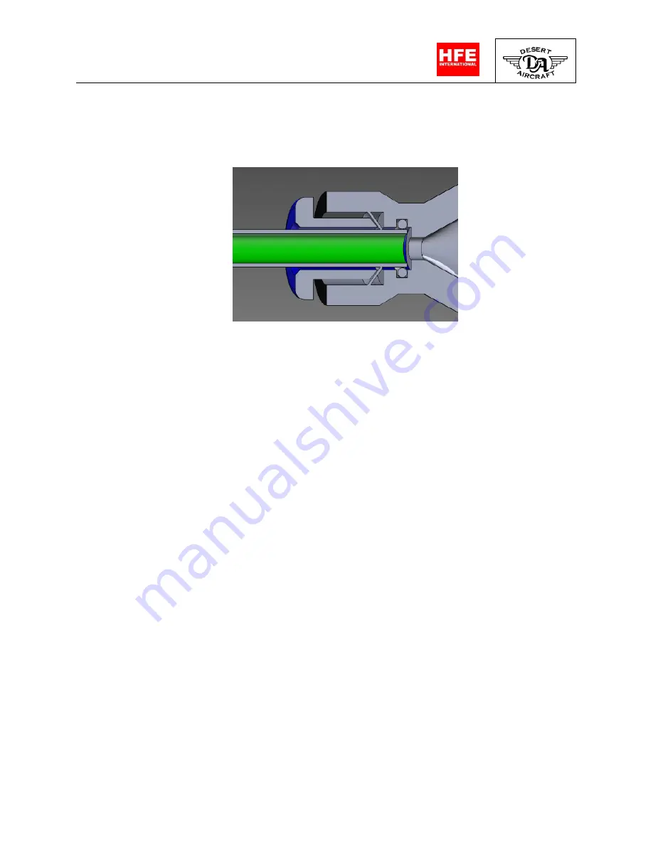
Figure 9:

 Push to Connect Diagram. Push tubing past  

 locking ring and O-ring to produce a proper seal. Push  

                              locking ring to release. 


5.


Install the green fuel filter between the fuel pump inlet and the fuel tank. 

6.


Install the blue filter between the fuel pump and the engine. 


FUEL SYSTEM WARNINGS  
Do not connect the fuel port to the Manifold Air Pressure tube. 

Do not exceed 15 PSI (1 bar) of fuel pressure. 

3b. Transmitter/Receiver Set Up


1.


Throttle commands use the standard output from Channel 3 of the receiver. 
Expected pulse width range from 900µs for closed throttle and 2100µs for wide 
open throttle. You may need to extend the end limits for channel 3 in your 

transmitter to produce the appropriate range. Adjust the exponential rate to get 
the desired throttle response. 

2.


(

Throttle kill

) Using the DA EFI system does not require an opto-kill switch for 

proper operation. When the pulse width from the receiver falls below 960µs (5% 

Summary of Contents for DA50 EFI

Page 1: ...DA50 EFI Electronic Fuel Injected Engine OWNER S MANUAL ...

Page 2: ...test revision Document Revision Table Rev Description of change Revised by Revision Date Approved By Approved Date A Initial Release DMcClain 01 16 19 TWest 01 16 19 B Update Spark Plug Callout DMcClain 07 29 19 DRB 7 31 19 C Format and part list update R Shoemaker 2 11 20 DRB 2 12 20 ...

Page 3: ...n Page 1 General Safety 4 2 Un Packing Your Engine 5 3 Getting Started 10 a Hardware Installation 10 b Transmitter Receiver Set Up 11 c Starting Engine 12 4 Maintenance 13 5 ECM Signal Data 14 a Blink Patterns 15 6 Technical Specifications 16 a Battery Recommendations 16 7 Warranty Information 17 8 Replacement Pats List 19 ...

Page 4: ...ect is allowed to enter Install a guard around the propeller when appropriate WARNING 1 Observe all safety precautions when working around the propeller 2 Exhaust contains poisonous carbon monoxide a colorless and odorless gas Breathing carbon monoxide can cause loss of consciousness and may lead to death 3 Never run your engine in an enclosed space Always allow for appropriate ventilation 4 Obser...

Page 5: ...ne Control Module ECM 3 Engine Wire Harness 4 ECM Input Harness 5 Owner s Manual 6 Mufflers If Ordered 7 Installation hardware 8 Fuel Pump 9 Air Filter 10 Ignition and ECM mounting kit ATTENTION Observe Precautions for Handling Electrostatic Sensitive Devices ESD The ECM and Throttle servo on this engine contain sensitive electronic hardware As a result this engine is packaged in electrostatic dis...

Page 6: ...uments folder for latest revision EFI Components and Descriptions Figure 1 Engine Control Module ECM Figure 2 ECM Input Harness from Receiver 14 Pin ECM Receptacle 24 Pin ECM Receptacle MAP Inlet 14 Pin ECM Plug Fuel Pump CH 3 Servo Throttle Tach Output Battery 12V ...

Page 7: ... 3 Main Engine Harness Figure 4 Assembly Hardware 24 Pin ECM Plug 13 Pin Engine Plug Ignition Crank Sensor Exhaust Gaskets square holes Fuel line between fuel tank and fuel pump Vacuum line between ECM and engine Fuel line between engine and fuel pump Heat Shrink used to connect CHT sensor to wire harness ...

Page 8: ... REV C 8 See HFE Released Documents folder for latest revision Figure 5 Fuel Pump Figure 6 Engine and Crank Harness Crank Sensor Connector 13 Pin Engine Receptacle Fuel Out to Engine Fuel In from Fuel Tank Fuel Pump Electrical Connector ...

Page 9: ...50 EFI OWNER S MANUAL HFEDCN0374 REV C 9 See HFE Released Documents folder for latest revision Figure 7 Intake Components Figure 8 Throttle Body Gasket Order Throttle Servo Injector MAP Outlet Fuel Fitting ...

Page 10: ...parts gasoline to one part oil Fuel Recommendations The engine was calibrated with standard 87 octane gasoline a Hardware Installation 1 Do not install the ECM to the engine or motor mount The vibration will damage the hardware Route the ECM to a location inside the aircraft and mount it where vibration is minimal The ECM does not produce excessive heat and can be encapsulated in foam to isolate i...

Page 11: ...ue filter between the fuel pump and the engine FUEL SYSTEM WARNINGS Do not connect the fuel port to the Manifold Air Pressure tube Do not exceed 15 PSI 1 bar of fuel pressure 3b Transmitter Receiver Set Up 1 Throttle commands use the standard output from Channel 3 of the receiver Expected pulse width range from 900µs for closed throttle and 2100µs for wide open throttle You may need to extend the ...

Page 12: ...fuel line from the back of the throttle body Cycle the battery power to the ECM in 5 second intervals until fuel is flowing from the fuel line then re install the fuel line You should not have to complete the priming process again unless the engine fuel system is allowed to run dry or has been disconnected for any reason 4 The engine should be started using an external spinner or using a built in ...

Page 13: ...is purging all the air from the fuel system This may not be evident until you go to wide open throttle 4 Allow the engine to run for a few minutes at idle around 3000 RPM 5 Verify all systems are functioning properly The engine is now ready for flight Flood Clearing If the engine is flooded increase the throttle above 50 and turn the engine over for 5 seconds Return the throttle to 25 30 and proce...

Page 14: ...power supply output from the Engine Control Unit for the crank sensor 13 SERVO GND Throttle servo ground 14 CRANK GND Crank sensor ground 15 SERVO SIGNAL Throttle position with logic level output A Pulse Width Modulated PWM signal at nominally 100Hz with ON time ranging from 900µs to 2100µs corresponding to throttle position This pin has an 8mA draw 16 CRANK SIGNAL 5V logic level digital input Bi ...

Page 15: ...gnal at nominally 50Hz with ON time ranging from 900µs to 2100µs corresponding to throttle position 0 to 100 This pin has an 8mA draw 10 GND Throttle input ground reference 11 ENABLE Special feature available on request Engine enable signal from AP A 5 volt signal present to enable UAV option only This pin has an 8mA draw 10k pull down resistor 12 GND Enable ground reference 13 MAIN GND Main Groun...

Page 16: ... 70 in lbs Aluminum cylinder base bolts M5x13mm 70 in lbs Throttle Body mounting bolts M5x40mm 20 in lbs Caution Care must be taken to not over tighten the TBI mounting bolts Over tightening can distort and damage the injected molded reed valve parts rubber gaskets and throttle body 6a Battery Recommendations Any 3 cell LiPO battery or equivalent battery pack with an amp hour capacity of 2000mA hr...

Page 17: ... Desert Aircraft starting from the date of purchase This warranty covers defects in workmanship and materials only Do not disassemble the motor or ignition system Disassembly of the motor or ignition system can void the warranty on that item Any modifications to the motor or the ignition system other than those authorized by Desert Aircraft will void this warranty This warranty does not cover the ...

Page 18: ...le body Do not disassemble the ECM or Throttle Body assembly Disassembly of the ECM or Throttle Body assembly will void the warranty on that item Any modifications to the ECM or Throttle Body assembly other than those authorized by HFE International will void this warranty This warranty does not cover the following Shipping expenses to and from HFE International for warranty service Damage caused ...

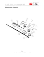
Page 19: ...DA 50 EFI OWNER S MANUAL HFEDCN0374 REV C 19 See HFE Released Documents folder for latest revision 8 Replacement Parts List ...

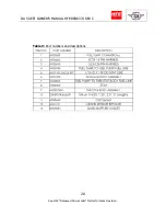
Page 20: ...DA 50 EFI OWNER S MANUAL HFEDCN0374 REV C 20 See HFE Released Documents folder for latest revision Table V Part numbers and descriptions ...

Reviews: