17
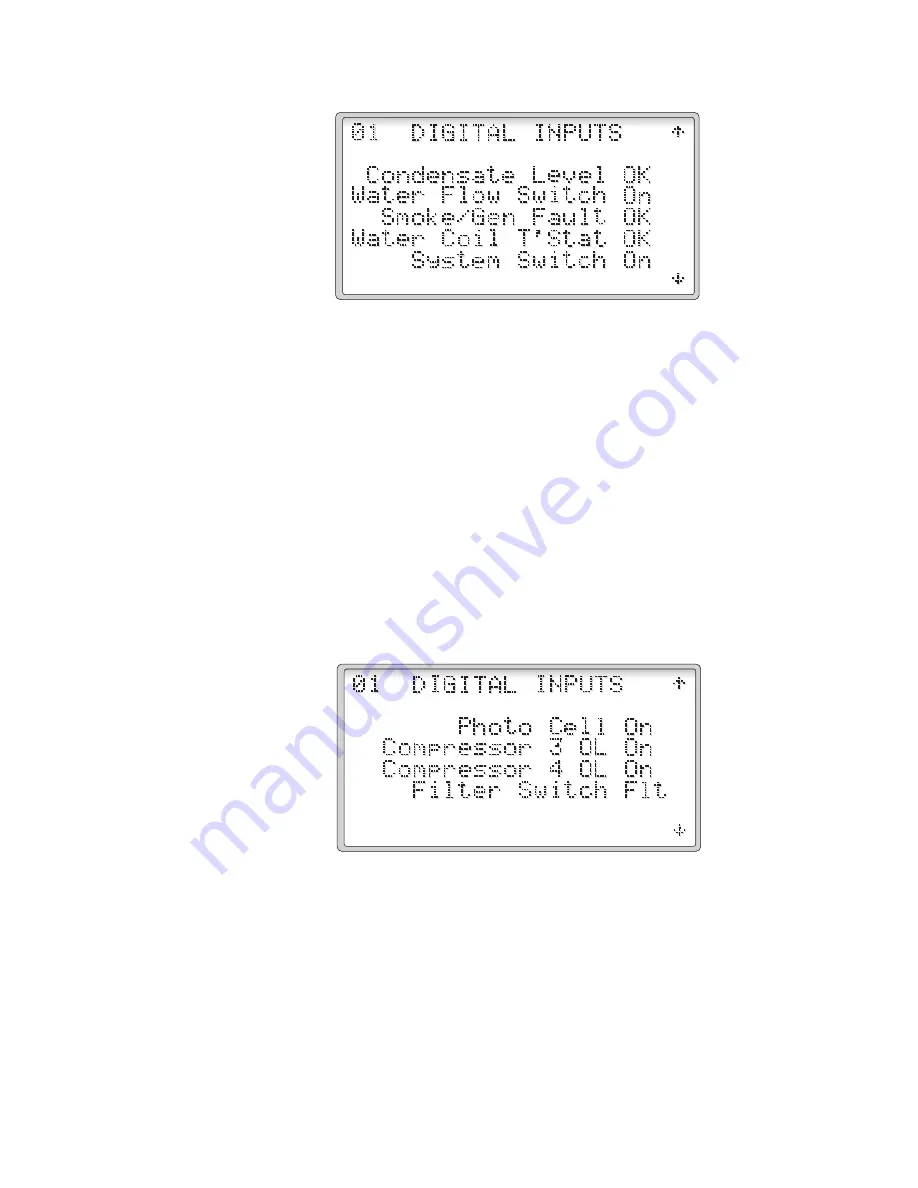
Figure 9
The third page of the Digital Inputs shows the status of the last four
contacts wired to the controller.
• The first line will show the status of ID11, the photo cell, “On” if
there is no light, and “Off” if there is light.
• The second line will show the status of ID12, compressor 3 motor
starter overload contacts, “OK” if no overload is present, and “Flt” if
an overload exists.
• The third line will show the status of ID13, compressor 4 motor
starter overload contacts, “OK” if no overload is present, and “Flt”
if an overload exists.
• The fourth line will show the status of ID14, the filter switch, “OK”
if the pressure drop is low, and “Flt” if the pressure drop is high.
Figure 10
The return to the I/O STATUS MENU, press the
Esc
key.
2.3.1.2.2 Analog Inputs (Figures 11-15)
Selecting the Analog Inputs Screens shows the state of the
sensors used by the control system. The first page shows the
suction and discharge pressure, the intake sensor RH and
Temperature readings as well as the supply air temperature
sensor.
Desert Aire - CM3550 Manual
Summary of Contents for CM3550 Series
Page 2: ...2 ...
Page 5: ...5 Desert Aire CM3550 Manual Product Warning for the State of California ...
Page 6: ...6 Desert Aire CM3550 Manual ...
Page 34: ...34 Figure 47 Figure 48 Figure 49 Figure 50 Desert Aire CM3550 Manual ...
Page 44: ...44 Desert Aire CM3550 Manual ...
Page 57: ...57 Desert Aire CM3550 Manual ...


