12-6 Digital I/O
XL™ Series
If the conditional statement needs to be greater than 48 characters, the user may enter one of the
40 user definable functions as the conditional statement and enter the real conditional statement
in the selected user defined function.
The default conditional statement for this option is the number ‘0' which basically disables the
trigger condition as 0.0 by itself equates to 0.0 or false.
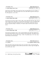
PC Interface View Built In Display Screen
C - Pulse Length = 1000 mS
Pulse Length [1000]
This option sets the pulse duration of the output when the mode is set to “Trigger Pulse.” This
value is in milliseconds, and the value can range from 1 millisecond to 9.999 seconds. The
default value is 1000 milliseconds (1 second).
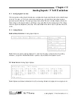
PC Interface View Built In Display Screen
D - Warm Up Delay = 250 mS
WarmUp Delay [ 250]
When the mode is “On For Scan,” the warm up delay sets a time delay between when the output
goes high and when the scan process continues on. This pauses the scanning process to allow for
sensors to warm up or stabilize for proper operation with the XL™. This value is in milliseconds,
and the value can range from 1 millisecond to 9.999 seconds. The default value is 250
milliseconds.
An example application where this option could be used is for a motor that needs to be turned on
at each scan but requires a delay of 2 seconds before the sensors are scanned. For this application,
the warm up delay would be set to 2000.
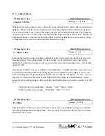
PC Interface View Built In Display Screen
1 - Test Output 1
Not Available In This Area Of
The Built In Menu
This section only describes how the test the output using the PC interface. To test the I/O using
the buitl in menu see the section above. When the digital I/O pin is configured as an output,
pressing the 1 key will activate the pin for testing purposes. If the pin is configured for pulsed
output, the output will turn on for the defined pulse length and then turn off again. If the pin is
configured for continuous operation, pressing the 1 key will cause the output to toggle between
high and low.
Summary of Contents for H-350XL
Page 1: ...XL Series Models H 350XL H 500XL H 510XL H 522 H 522 Plus Owner s Manual ...
Page 30: ...2 16 Hardware Options and Installation XL Series ...
Page 42: ...3 12 Using The Built In Keypad Display XL Series ...
Page 46: ...4 4 PC Menu Interface Operation XL Series ...
Page 58: ...5 12 Miscellaneous System Setup XL Series ...
Page 66: ...6 8 Serial Port Options XL Series ...
Page 74: ...7 8 System Configuration Files XL Series ...
Page 84: ...8 10 System Status Menus Options XL Series ...
Page 88: ...9 4 Scanning Options XL Series ...
Page 156: ...15 12 Logging Options XL Series ...
Page 198: ...16 42 Operation with the GOES Radio XL Series ...
Page 216: ...19 6 Alarm Call Out XL Series ...
Page 234: ...21 8 Operation with the H 355 Smart Gas System XL Series ...
Page 246: ...22 12 Functions XL Series ...

