XL™ Series
SDI-12 Operations 14-17
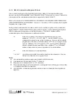
14.7.1 SDI-12 Command and Response Protocol
This is a brief description of the Serial Digital Interface (SDI-12) Command and Response
protocol used by the
W
ATER
LOG
Series Model H-350XL™ when used as a sensor. Included is
®
a description of the commands and data format supported by the H-350XL™.
Refer to the document "A SERIAL DIGITAL INTERFACE STANDARD FOR HYDROLOGIC
AND ENVIRONMENTAL SENSORS." Version 1.1 November, 1993 Coordinated by Campbell
Scientific, Inc., Logan, Utah.
During normal communication, the data recorder sends an address together with a command to
the H-350XL™. The H-350XL™ then replies with a "response". In the following descriptions,
SDI-12 commands and responses are enclosed in quotes. The SDI-12 address and the
command/response block terminators are defined as follows:
"a"
Is the sensor address. The following ASCII Characters are valid
addresses: "0" to "9", "A" to "Z", and "*". The H-350XL™ can be
configured to respond to any of the 36 addresses. Sensors will be initially
programmed at the factory with the address of "0" for use in single sensors
systems. Addresses "1" to "9" and "A" to "Z", can be used for additional
sensors connected to the same SDI-12 bus. Address "*" is a "wildcard"
address which selects any sensor, regardless of its actual address.
"!"
Is the last character of a command block.
"<cr><lf>"
Are carriage return (0D) hex and line feed (0A) hex characters. They are
the last two characters of a response block.
Notes:
!
All commands/responds are upper-case printable ASCII characters.
!
Commands must be terminated with a "!" character.
!
Responses are terminated with <cr><lf> characters.
!
The command string must be transmitted in a contiguous block with no gaps of more than
1.66 milliseconds between characters.
!
All ASCII-Hex commands, arguments and data values are transmitted most significant
digit first.
Summary of Contents for H-350XL
Page 1: ...XL Series Models H 350XL H 500XL H 510XL H 522 H 522 Plus Owner s Manual ...
Page 30: ...2 16 Hardware Options and Installation XL Series ...
Page 42: ...3 12 Using The Built In Keypad Display XL Series ...
Page 46: ...4 4 PC Menu Interface Operation XL Series ...
Page 58: ...5 12 Miscellaneous System Setup XL Series ...
Page 66: ...6 8 Serial Port Options XL Series ...
Page 74: ...7 8 System Configuration Files XL Series ...
Page 84: ...8 10 System Status Menus Options XL Series ...
Page 88: ...9 4 Scanning Options XL Series ...
Page 156: ...15 12 Logging Options XL Series ...
Page 198: ...16 42 Operation with the GOES Radio XL Series ...
Page 216: ...19 6 Alarm Call Out XL Series ...
Page 234: ...21 8 Operation with the H 355 Smart Gas System XL Series ...
Page 246: ...22 12 Functions XL Series ...


