background image

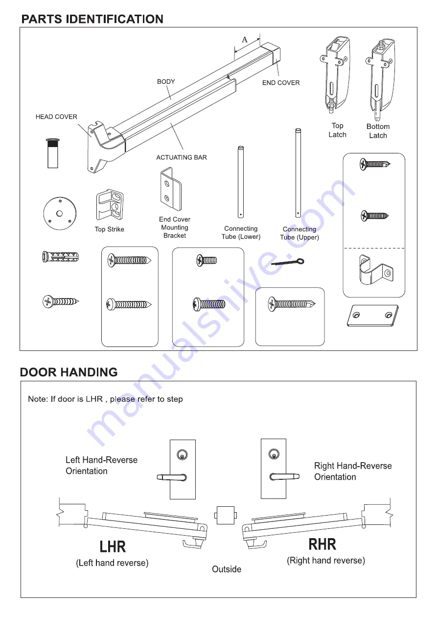
Latchbolt Filler  Plate

Rod Guide (2PCS)

Wood Screws

5/32”x 3/4” (4 PCS)

5/32”x 3/4” (4 PCS)

,Self Tapping


Pin (2 PCS)

Flat Head

Flat Head

1/4”x 1 1/4” (6 PCS)


Round Head

Round Head

1/4”x 1 ” (6 PCS)

Wood Screws

Wood Screws

Flat Head

Floor Strike 

Thru Bolt (12 PCS)

Machine Screws

Machine Screws

   Flat  Head

1/4”-20P x 3/4” (12 PCS)

1/4”-20P x 3/4” (3 PCS)

14#x1 1/2” (15 PCS)


Machine Screws

,Self Tapping

Flat Head

5/32”x3/4” (3 PCS)

1/4” x 1” (3 PCS)

Anchor

Assembly

1

Assembly

IF DOOR IS LESS THAN 36", REMOVE 

END COVER AND CUT SECTION "A" 

TO DESIRED LENGTH.

Summary of Contents for F2000V Series

Page 1: ...F FIRE RATED EXIT DEVICE 2012 03 ...

Page 2: ...hown on template Mark door as indicated on template B 2 CAUTTON BE SURE THE DISTANCE FROM BOTTOM SIDE OF DOOR EDGE TO BOTTOM OF BOTTOM LATCH ASSEMBLY IS 13 32 2 Tighten screws to install bottom latch assembly STEP 6 INSTALL TOP LATCH ASSEMBLY 1 Align vertical center line of top latch assembly and upper connecting tube as shown on template B 1 Mark door as indicated on template B 1 CAUTION BE SURE ...

Page 3: ... 4 dia 1 1 8 deep 5 Hammer 3 anchors into 3 anchor screw holes Tighten up 3 screws STEP 13 INSTALL 4 COVERS Install head cover end cover top latch cover bottom latch cover and tighten screws STEP 8 INSTALL AND ADJUST UPPER CONNECTING TUBE 1 Keep the end of the tube with the threaded insert upward to connect it with the threaded bolt in the top latch assembly 2 Connect the other end of the tube to ...

Page 4: ...Round Head 1 4 x 1 6 PCS Wood Screws Wood Screws Flat Head Floor Strike Thru Bolt 12 PCS Machine Screws Machine Screws Flat Head 1 4 20P x 3 4 12 PCS 1 4 20P x 3 4 3 PCS 14 x1 1 2 15 PCS Machine Screws Self Tapping Flat Head 5 32 x3 4 3 PCS 1 4 x 1 3 PCS Anchor Assembly 1 Assembly IF DOOR IS LESS THAN 36 REMOVE END COVER AND CUT SECTION A TO DESIRED LENGTH ...

Page 5: ...e B For F2000V Fire Rated Drill 9 32 holes inside and 3 8 holes outside for the 6 thru bolts Round Head Screws 1 4 20P x 3 4 x 6 Round Head Screws 2012 03 3 4 for LE 08 LE 08A Trim 3 4 for LE 08 LE 08A Trim 2 3 4 2 3 4 When installing 1000R x 1000V on a pair of doors a Double Door Strike DDS is required For complete template information please refer to the DDS template CENTER LINE CENTER LINE ...

Page 6: ...e and install screw but do not tighten all the way 2 Drill 2 D holes and install and tighten screws 3 Tighten screw in hole E all the way 2012 03 TEMPLATE B 2 A For 2000V Series UL Listed Drill tap for 3 1 4 20P x 3 4 machine screws 2xD E for latches Drill 3 3 16 pilot holes 2xD E for self tapping machine screws or wood screws for latches B For F2000V Fire Rated Drill 9 32 holes 2xD E inside and 3...

Page 7: ...ll the way 2 Make sure distance from door frame to line W is 2 3 Drill 2 D holes and install and tighten screws 4 Tighten screw in hole E all the way A For 2000V Series UL Listed Drill tap for 3 1 4 20P x 3 4 machine screws 2xD E for latches Drill 3 7 32 pilot holes 2xD E for self tapping machine screws or wood screws for latches B For F2000V Fire Rated Drill 9 32 holes 2xD E inside and 3 8 holes ...

Reviews: