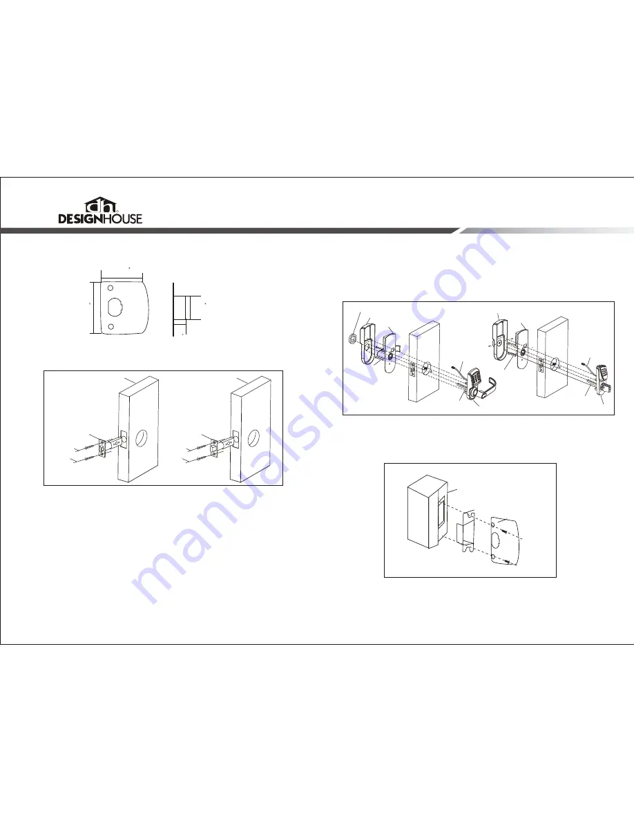
3. Insert latch to prepared door and attached with two (3.5x3/4" / 3.5x20MM)
screws. See Fig. 1.
4. Install 4 (AA) alkaline batteries in the Battery Box on the Interior Panel.
5. Feed the power wire from the Exterior Panel (with keypad) through the door hole (A)
and latch (see Fig. 2). Connect the power wire to the battery box.
6. Attach the Exterior Panel making sure the lock Spindle is squarely inserted into mount-
ing plate on Interior Panel through door hole (A). Be sure to secure the metal panels
to the inner edges of the rubber gaskets for a sealed installation on both the interior
and exterior sides.
7. Attach the Exterior Panel and the Interior Panel with two (4x1-3/8 / 4x35MM) or
1.97" / 4x50MM) screws depending on different door thicknesses.
8. Attach the Interior Cover Plate over the Battery Box and Interior Panel.
(4x
10. Place Plastic Insert into prepared hole on door frame. Attach Strike Plate
with two self-tapping screws.
11. Verify that the Door Latch engages with the Strike Plate on the doorframe.
K
EYPAD
L
OCK
2. Drill and prepare the doorframe for the Plastic Insert and Strike Plate making
sure the holes are level and a direct match for the door lock drilling (See Fig. A).
Page.5
Page.6
Fig.A.
1-3/4
(44mm)
2-1/4
(57mm)
1-1/8
(28mm)
1/2
(13mm)
Fig.3
Door frame
Plastic Insert
Strike Plate
Fig.1
3.5x20mm screw
3.5x20mm screw
Regular Latch
Deadbolt
Door panel
R
4*35mm screw
Interior cover plate
Interior panel
Fig. 2
B
C
4*35mm screw
Interior cover plate
Interior panel
Cover loop
power wire
Exterior Panel
Spindle
Keypad Lever Entry
3.5x20mm screw
3.5x20mm screw
Door panel
B
C
power wire
Exterior Panel
Spindle
Keypad Deadbolt Entry
9. Feed Cover Loop and plastic gasket ring over the interior handle. Screw Cover Ring
tightly to secure the interior assembly.(Lever Entry Only)
Attach the Interior Cover onto the Interior Panel and fix them with two (3x10mm)
screws on both sides of Interior Cover.See Fig.2. (Deadbolt Entry Only)


